Posted on Leave a comment

Precautions for using fiber jumpers

Precautions for using fiber jumpers

Across the fiber jumpers, optical module transceiver wavelength must be consistent, i.e. the fiber ends must be the same wavelengths of the light module, a simple distinction is the color of the light module to be consistent. In general, short-wavelength optical modules use multimode fiber (orange fiber), and long-wavelength optical modules use single-mode fiber (yellow fiber) to ensure data transmission accuracy.

Do not bend or wrap the fiber in use, which will increase the attenuation of light during transmission.

After the fiber jumper is used, the fiber connector must be protected with a protective cover. Dust and oil can damage the coupling of the fiber.

If the fiber connector is dirty, you can use a cotton swab to clean the alcohol, otherwise, it will affect the communication quality.

1. The fiber jumper ceramic ferrule and the ferrule end face must be wiped clean with alcohol and absorbent cotton before use.

2. The minimum bending radius of the fiber is less than 30mm when in use.

3. Protect the ferrule and the ferrule end face to prevent bumps and pollution, and bring the dust cap in time after disassembly.

4. Do not look directly at the fiber end face when the laser signal is transmitted.

5. In case of damage caused by man-made and other force majeure factors, the damaged fiber jumper should be replaced in time.

6. Read the instructions carefully before installation and install and debug under the guidance of the manufacturer or dealer.

7. If an abnormal situation occurs in the optical network or the system, the fault elimination method can be used to test one by one. You can do the continuity test when testing or troubleshooting the jumper. You can usually use the visible laser pointer to judge the entire fiber link. Or further, use the precision fiber insertion loss detector to test its various indicators. If the indicator is within the qualified range, the jumper indication is normal, otherwise, it is unqualified.


Posted on Leave a comment

What are the differences between fiber patch cords and copper wires?

What are the differences between optical fiber jumpers and copper wires? With the development of the times, optical fibers have gradually replaced copper wires as the mainstream connecting devices. Of course, there are always more controversies in the choice of optical fibers and copper wires, and even Many friends think that the delay of the fiber line is shorter than the delay of the copper wire. So, what are the differences between the fiber jumper and the copper wire?

What are the differences between fiber patch cords and copper wires?

1. What are the differences between fiber jumpers and copper wires?

Optical fiber and copper wire are two common data center transmission media, both of which have anti-interference and good confidentiality. So what is the difference between fiber and copper wire? The difference between the two is mainly reflected in the following four aspects:

1. Transmission distance

Generally speaking, the transmission distance of copper wire does not exceed 100m, and the maximum transmission distance of fiber can reach 100km (single mode fiber), which far exceeds the transmission distance of copper wire.

2. Transmission rate

At present, the maximum transmission rate of copper wire can reach 40Gbps (such as eight types of network cable, DAC passive copper cable), and the maximum transmission rate of optical fiber can reach 100Gbps (such as OM4 fiber jumper), far exceeding copper wire.

3. Maintenance management

The operation of the crystal head of the copper wire and the port connection of the device is very simple, and the operations of shear welding and equipment connection of the optical fiber are required to be high and the operation is complicated.

4. Price cost

In the case of the same length of fiber and copper wire, the price of fiber is generally 5-6 times the price of copper wire, and the price of fiber-optic plug-in equipment (such as fiber coupler) is much higher than that of copper wire. In terms of price cost, the price cost of fiber is much higher than the price of copper wire.

Second, how the delay of the fiber jumper and copper wire

1, fiber jumper

Because fiber is currently used more, let’s first look at the delay of the fiber.

Physical knowledge, the speed of light in a vacuum is 3 * 10 8 square meters/sec, the speed of light will be slower under air conditions. Therefore, when an optical signal propagates in a fiber link, there are five steps to wait: the electrical signal is converted into an optical signal to produce two; the optical signal is generated through the optical fiber, and the optical signal is converted into an electrical signal to produce two.

2, copper wire

The signal quality of copper wires is not as good as that of optical fibers. Especially in long-distance transmission, signals are easily interrupted by the surrounding environment. The longer the distance, the more severe the attenuation. Frequently caused by client loss, page faults, slow user opening, etc.

Third, the delay of fiber jumper and copper wire contrast

The difference in delay between fiber and copper wire theoretically means that the signal is transmitted faster in the copper wire, but under long-distance demand, the signal processing and repetition requirements are less, the fiber delay is lower, and the copper wire is susceptible to the outside. The interference, the loss is large, and the delay is also larger.

In fact, we don’t have to delay to describe the fiber and the network, which are described by distance and speed. Different distances and speed delays are different. For example, serializing a 150-byte packet on a 1.5 Mbps link requires 8 ms, while at 10 Gbps it only requires 1.2 us, and at high speeds, there is less latency.

For the difference between the fiber jumper and the copper wire, I would like to see that the friends here have already got a certain understanding of this. In fact, the difference in delay between the fiber jumper and the copper wire is affected by the speed and distance. In the choice of the fiber jumper and the copper wire, if the distance is short, we can choose the copper wire as the transmission medium, the cost. It will be much lower than the fiber jumper. On the contrary, if it is transmitted over long distances, we can choose the fiber as the transmission medium, and its performance will be more stable.

(This article is from the Internet, compiled and edited by thousands of hackers. If there is any infringement, please contact to delete.)

Original Article Sourcehttp://cabling.qianjia.com/html/2019-04/01_331517.html

Posted on Leave a comment

Common fault solving method for weak engineering optical fiber transceiver

Foreword:

Our commonly used fiber optic transceivers have 6 indicators, so what does each indicator mean? Do all the indicators light up to indicate that the fiber transceiver is working properly?

PWR: Lights up to indicate that the DC5V power supply is working properly.

FDX: Lights up to indicate that the fiber transmits data in full duplex mode;

FX 100: Lights up to indicate that the optical fiber transmission rate is 100Mbps;

TX 100: The light is on, indicating that the twisted pair transmission rate is 100 Mbps, and the light is off, indicating that the twisted pair transmission rate is 10 Mbps;

FX Link/Act: The long light indicates that the fiber link is connected correctly; the flashing light indicates that data is being transmitted in the fiber;

TX Link/Act: The long light indicates that the twisted pair link is connected. When the light is on, the data in the twisted pair is transmitted at 10/100M.

If the optical transceiver is working properly, the PWR power indicator must be steady on. The FX-LINK/ACT fiber link indicator and the TX-LINK/ACT network link indicator must be on or blinking. If the LINK/ACT indicator is off. Check whether the link is normal. The FDX working mode indicator, FX-100 fiber rate indicator and TX-100 network rate indicator are not on the fiber transceiver.

1. The function of the indicator light of the optical transceiver and the method for determining the fault

1. First, do you see if the indicator of the fiber transceiver or optical module and the twisted pair port indicator are on?

  • A. If the optical port (FX-LINK/ACT) indicator of the transceiver is not lit, please confirm whether the fiber link is correct cross-link, fiber-optic jack TX-RX; RX-TX.
  • B. If the optical port (FXFX-LINK/ACT) indicator of the A transceiver is on and the optical port (FXFX-LINK/ACT) indicator of the B transceiver is not lit, the fault is on the A transceiver side: one possibility is: The A transceiver (TX) optical transmission port is broken because the optical port (RX) of the B transceiver does not receive the optical signal; the other possibility is that the optical link of the A transceiver (TX) optical transmission port has Problem (the cable or fiber jumper may be broken).
  • C. The twisted pair (TXFX-LINK/ACT) indicator does not light. Please make sure that the twisted pair cable is faulty or connected incorrectly? Please use the continuity tester (although some transceivers’ twisted pair indicators must be on after the fiber link is connected).
  • D. Some transceivers have two RJ45 ports: (To HUB) indicates that the connection line connecting the switches is a straight-through line; (To Node) indicates that the connection line connecting the switches is a cross-line.
  • E. Some transceivers have an MPR switch on the side: the connection line connecting the switch is a straight-through mode; the DTE switch: the connection line connecting the switches is a cross-line mode.

2. Is the optical cable and fiber jumper broken?

  • A. The cable on/off detection: use laser flashlight, sunlight, illuminator to illuminate one end of the cable connector or coupler; see if there is visible light on the other end? If there is visible light, the cable is not broken.
  • B. Optical fiber connection continuity detection: use laser flashlight, sunlight, etc. to illuminate the fiber jumper; see if there is visible light on the other end? If there is visible light, the fiber jumper is not broken.

3. Is there a mistake in the half/full duplex mode?

Some transceivers have FDX switches on the side: full duplex; HDX switches: half duplex.

4, using optical power meter instrument detection

The luminous power of a fiber optic transceiver or optical module under normal conditions:

Multimode 2Km: between -10db and 18db;

Single mode 20 km: between -8 dB and 15 dB;

Single mode 60 km: between -5db and 12db;

If the luminous power of the optical transceiver is between -30db and 45db, then it can be judged that there is a problem with this transceiver.

Second, common faults and solutions

According to the daily maintenance and the problems that the users have summed up, I hope to bring some help to the maintenance staff, to determine the cause according to the fault phenomenon, to find the fault point, “the right medicine.”

1. What kind of connection is used when the transceiver RJ45 port is connected to other devices?

Cause: The RJ45 port of the transceiver is connected to the PC network card (DTE data terminal equipment) using a crossover twisted pair, and the HUB or SWITCH (DCE data communication equipment) uses parallel lines.

2. What is the reason why the TxLink light is not lit?

answer:

  • 1, wrong twisted pair
  • 2, the twisted pair crystal head is in poor contact with the equipment, or the quality of the twisted pair itself
  • 3, the device is not connected

3. What is the reason why the TxLink lamp does not flash but is always on after the fiber is normally connected?

the reason:

  • 1. The fault is generally caused by the transmission distance being too long;
  • 2, compatibility issues with the network card (connected to the PC)

4. What is the reason why the Fxlink light does not illuminate?

the reason:

  • 1. The fiber optic cable is connected incorrectly, and the correct connection method is TX-RX, RX-TX or fiber mode is wrong;
  • 2. The transmission distance is too long or the intermediate loss is too large, exceeding the nominal loss of the product. The solution is to take measures to reduce the intermediate loss or replace it with a transmission distance longer.
  • 3. The operating temperature of the fiber optic transceiver is too high.

5. What is the reason why the Fxlink light does not flash but is always bright after the fiber is connected normally?

Cause: The fault is generally caused by the transmission distance being too long or the intermediate loss is too large, exceeding the nominal loss of the product. The solution is to minimize the intermediate loss or replace it with a transceiver with a longer transmission distance.

6. What should I do if the five lights are all on or the indicator is normal but not transferable?

Reason: Generally, the power is turned off and restarted.

7. What is the ambient temperature of the transceiver?

Cause: The fiber optic module is greatly affected by the ambient temperature. Although it has its own built-in automatic gain circuit after the temperature exceeds a certain range, the optical power of the optical module is affected and decreased, which weakens the quality of the optical network signal and causes packet loss. The rate rises and even disconnects the optical link; (typical fiber optic modules can reach 70°C)

8. What is the compatibility with the external device protocol?

the reason:

Like the 10/100M switch, the 10/100M optical transceiver has a certain limit on the frame length, generally not exceeding 1522B or 1536B. When the switch connected at the central office supports some special protocols (such as Ciss ISL), The packet overhead is increased (the packet cost of the ISL of the Ciss is 30 Bytes), which is exceeded by the upper limit of the frame length of the optical transceiver. This indicates that the packet loss rate is high or not. In this case, the MTU of the terminal device needs to be adjusted. The overhead of the general IP packet is 18 bytes, and the MTU is 1500 bytes. Currently, the high-end communication equipment manufacturer has an internal network protocol, which generally adopts a separate packet method, which will increase the overhead of the IP packet. If the data is 1500 bytes, IP. After the packet, the size of the IP packet will exceed 18 and be discarded), so that the size of the packet transmitted on the line is satisfactory to the network device’s limitation on the frame length.

9. After the chassis has been working normally for a while, why is it that some cards are not working properly?

the reason:

Early chassis power supplies used relays. Insufficient power supply margin and large line loss are major problems. After the chassis works normally for a period of time, some cards may not work properly. When some cards are pulled out, the remaining cards work normally. After the long-term operation of the chassis, the connector oxidation causes a large joint loss. This power supply falls beyond the regulations. The required range may cause the chassis card to be abnormal. The power supply switching of the chassis is protected by a high-power Schottky diode to improve the form of the connector and reduce the power drop caused by the control circuit and the connector. At the same time, the power redundancy of the power supply is increased, which makes the backup power supply convenient and safe, and makes it more suitable for the long-term uninterrupted work.

10. What function does the link alarm provide on the transceiver?

Cause: The transceiver has a linked alarm function (linkless). When a certain fiber is dropped, it will be automatically fed back to the electrical port (that is, the indicator on the electrical port will also be extinguished). If the switch has network management, it will be reflected in the switch immediately. Network management software. Third, the fiber transceiver should pay attention to matters

1. Does the optical transceiver itself support full-duplex and half-duplex?

Some chips on the market can only use full-duplex environment at present, and can’t support half-duplex. If you receive another brand of the switch (SWITCH) or hub (HUB), and it uses half-duplex mode, it must be It can cause serious conflicts and packet loss.

2. Have you tested the connection with other fiber optic transceivers?

At present, there are more and more optical transceivers on the market. For example, if the compatibility of transceivers of different brands has not been tested beforehand, it will also result in packet loss, long transmission, and rapid and slow.

3. Is there a safety device to prevent packet loss?

In order to reduce the cost, some manufacturers use the register data transmission mode when manufacturing the optical transceiver. The biggest disadvantage of this method is that the transmission is unstable and packet loss and the best is to use the buffer circuit design, which is safe. Avoid data loss.

4, temperature adaptability?

When the fiber optic transceiver itself is used, it will generate high heat. When the temperature is too high (not more than 50 °C), whether the fiber optic transceiver works normally is a factor worth considering when purchasing!

Original Article Sourcehttp://www.qianjia.com/html/2019-05/06_335742.html

Posted on Leave a comment

Familiar with 5G bearer requirements to grasp the optical module “pulse”

According to GSA statistics, as of the end of January 2019, 201 operators in 83 countries/regions tested, deployed or planned to deploy 5G. On April 3, South Korea’s three major operators and Verizon of the United States announced the opening of 5G commercial services for public users, and the 5G construction speeded up; on April 23, China Unicom announced the opening of 5G networks in 40 cities and officially released the 5G brand. It indicates that the domestic 5G construction is also accelerating.

1557026385668039846.png

Figure 4G/5G networking solution comparison

5G construction, bearer first, but the global operators’ 5G bearer solutions are different. Especially after the introduction of the concept of the middle pass, compatibility is considered whether to use independent networking, and the bearer scheme is more varied: for example, China Mobile adopts a new SPN network, China Telecom prefers to adopt M-OTN network, and China Unicom adopts IPRAN as the main mode of the bearer. Korean carriers and US carriers that are the first to be commercialized also use different bearer solutions. As is known, the complex bearer scheme will increase the number of corresponding 5G optical modules. However, according to the needs of the three major operators in China, there are certain contexts to be found.

In terms of speed, after the introduction of the eCPRI protocol standard, the pre-transmission 25G rate has become the standard of various equipment manufacturers. As a result, the rate of the bearer network will be considered according to the convergence ratio of each layer, and the 50G rate is the most The choice of cost performance, according to the development of the predecessor, there may be a module demand of 100G or even 200G rate.

In terms of fiber utilization efficiency, considering the difficulty of fiber laying, there is always a problem of tight fiber resources in some areas. Therefore, the BiDi module and even the WDM-based color light module will become a powerful complement to the requirements of the load module. The combination of speed, single/dual fiber and color light has resulted in a wide variety of 5G optical modules. Fortunately, the package form of the current mainstream optical module is basically based on QSFP28. Otherwise, the market for carrying optical modules will be more confusing.

As mentioned above, the 50G rate is the most cost-effective option for the middle pass, but from a module perspective, the 25G laser is the most popular rate choice for the industry chain. What should be done if there is a difference between the two? PAM4 technology solves this problem in a timely manner. It can double the amount of information transmitted per unit time through the algorithm of the electrical layer DSP at the same laser rate. Therefore, 50G PAM4 is based on a single 25G laser, and 50G rate signal transmission is realized by the electrical layer PAM4 technology. At present, the 50G PAM4 QSFP28 module is a typical requirement of the China Mobile network in the China Mobile SPN system. Guangxun Technology is the earliest optical module manufacturer in China to invest in 50G PAM4 LR/ER development. It is also involved in the discussion and formulation of China Mobile’s previous related standards. It is currently one of the few to provide a full range of 50G PAM4 products (10km single/dual fiber), 40km single/dual fiber) optical module manufacturers.

In addition, WDM color light modules are gaining more and more attention in 5G bearer solutions. Because in the foreign markets such as Japan and South Korea, the 4G era has begun to lay the bearer network of WDM solutions, and the continued selection of WDM modules in the 5G era is natural. At the same time, because the domestic 5G uses high-frequency signals, the coverage of the base station is small, and the number of 5G base stations will double that of the 4G era, which poses a great challenge for fiber laying. In terms of cost, although the cost of a separate module for WDM color light solutions is high, the cost of the overall solution will be more competitive.

Original Article Source http://www.qianjia.com/html/2019-05/06_335620.html

Posted on Leave a comment

LC: The global AOC and EOM market will reach $1.09 billion in 2023

ICCSZ News (Compile: Nina) LightCounting’s newly released active optical cable (AOC) and embedded optical module (EOM) market analysis and forecast report pointed out that in the next five years (2019-2023), the size of both markets will grow steadily , although AOC will be a little less energetic than before.

LC said the price decline will offset the increase in AOC shipments. For example, the latest report predicts that global AOC shipments in 2022 will be raised by about 30% from the previous year’s forecast. However, due to lower prices and higher demand for single-channel AOCs, revenue forecasts for 2022 are down 18% from the previous year’s report. LC expects the global AOC market to grow from $280 million in 2018 to $547 million in 2023.

LC said that China and other data center operators often use single-channel active optical cable (AOC) to connect servers to the first-tier switches, so they raised their expectations for single-channel AOC requirements. At the same time, Chinese data center operators typically do not use AOC to connect switches, thereby curbing the potential demand for Ethernet four-channel AOCs typically used in such applications.

The report pointed out that the high-performance computing (HPC) and data center areas are rapidly adopting 100G AOC, and it is expected that the HPC field will begin to develop into the 200G AOC this year. However, the market research company did not see the same enthusiasm for adopting the 200G Ethernet AOC in the data center market.

Regarding the EOM market, LC analysts believe that the technology will enter a good growth track after a decade of bumps. In the latest report, LC’s shipments to EOM are expected to increase by about 20% from the previous year’s analysis, and revenues have increased by 29%. The report’s authors expect that growth in this market will accelerate by 2020, with revenue increasing from $136 million in 2018 to $543 million in 2023.

Original Article Source http://www.qianjia.com/html/2019-01/07_319218.html

Posted on Leave a comment

Fiber access equipment and usage diagram

As the demand for different kinds of information is also increasing, the accompanying ever-increasing demand for new services such as IP data, voice, and multimedia images has prompted the network environment of major network operators to become overwhelming. In the past, traditional metropolitan area networks and access networks, which mainly used to carry analog voices, have been unable to meet the requirements of a variety of new service transmission and processing in terms of capacity and interface types. As a result of the rapid advancement of social information, the technologies and equipment that provide new services for metropolitan area networks and access networks have rapidly developed. Among them, the development of MSTP (Multi-Service Transport Platform) and PON (Passive Optical Network) is the most representative. They are based on fiber-optic transmission technology and provide the best of various new service bearers on the metropolitan area network or access network. solution.

Fiber-optic cable access technology is the development direction of broadband networks in the future. Its development is also inseparable from the development and support of fiber access equipment, just like fish and water. Talking about the fiber access equipment has to mention its three generations of development experience: the first generation of large-scale PDH (fiber optic transceiver) equipment, including point-to-point and star-type office equipment, does not have aggregation function. All adopt PDH transmission protocol, and there is no optical interface specification. User services, such as E1 and data services, are multiplexed through the private PDH protocol and transmitted to the central office equipment via optical fibers. The central office equipment taps the PDH optical signal according to the proprietary protocol, and converts it into a PDH interface such as E1, and then connects to the metro backbone/aggregation device through the cable through the DDF distribution frame. Due to the limitations of the PDH protocol, various types of fiber access devices are quickly out of date.

The second generation In view of the defects of the first generation equipment, some PDH equipment manufacturers have developed a piece of second generation equipment, that is, adding an SDH (dense optical wave multiplexing) terminal card to the central office equipment. The private PDH protocol is still used between the central office and the remote device, and the aggregation function is provided at the central office to multiplex the original E1 signal through the SDH terminal card and provide a standard SDH interface. It mainly solves the interconnection problem and unified interface standard between the central office equipment and the metro backbone equipment.

The third generation is SDH pass-through equipment, including converged and non-converged types. Due to the wide coverage of the new services, the new generation of SDH pass-through devices can be automatically adapted to the SDH for transmission according to the SDH specification. The non-aggregated remote device can be directly connected to the metropolitan area network aggregation layer node through the SDH optical interface. There are fewer service interfaces on the aggregation layer network. The aggregation type is inserted into the SDH aggregation device at the central office to aggregate VC12 services from multiple directions to the uplink SDH interface, thus saving the number of STM-1 interface cards on the large-capacity backbone node device. It mainly solves the compatibility problem of each device and is convenient for future upgrade and maintenance.

With the development of fiber access equipment to date, due to the continuous updating of fiber access technologies and the increasing number of manufacturers joining, the categories of fiber access equipment are becoming more and more obvious, mainly in three categories:

(1) Optical fiber communication Continued text components (for communication and computer network terminal connections), such as fiber jumpers, fiber connectors (boxes).

(2) Optical fiber transceiver (for computer network data transmission), such as fiber optic box, fiber coupler and wiring box (rack).

(3) Optical cable engineering equipment, optical cable test instrument (for large-scale engineering), such as optical fiber fusion splicer, optical fiber loss test equipment.

For the first two categories, we can often understand and contact the fiber access equipment products. The following small series introduces two major types of equipment:

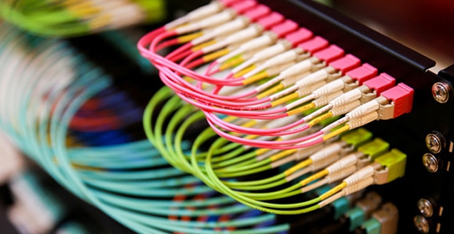
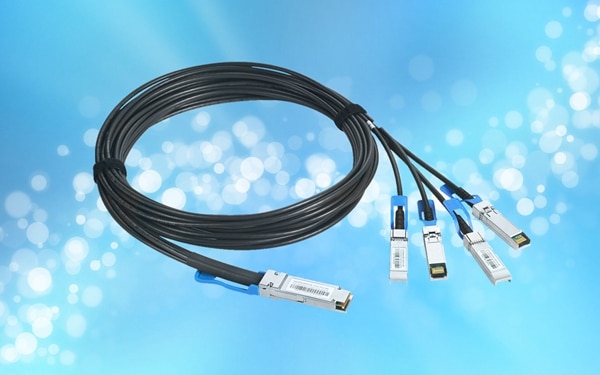
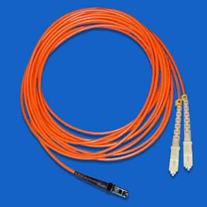
fiber optic communication and text fiber transceivers: the fiber jumper is without connection. The cable pair or cable unit of the unit is used to interface with various links on the distribution frame. Fiber optic patch cords are used for long-haul and local optical transmission networks, data transmission and private networks, and various test and automation systems.

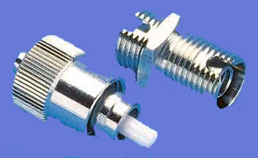
  Fiber optic connector (box)

fiber optic connector (box) is mainly used for the connection between fiber and fiber, fiber and device.

  Fiber optic boxes

Fiber optic boxes are used to transmit digital and similar voice, video and data signals using fiber optic technology. Fiber optic boxes are available for direct or desktop installation. Particularly suitable for high-speed fiber transmission.

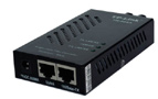
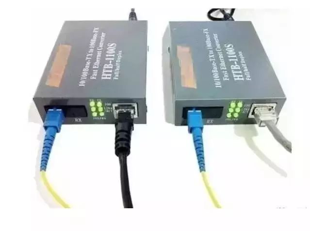
  The product shown above is a 100Base-TX twisted pair 100Base-FX multi/single mode fiber optic repeater designed primarily for Fast Ethernet workgroup users who require a long distance, high speed, and wide bandwidth.

  The product shown above is a 10/100M adaptive Fast Ethernet fiber optic transceiver. It can realize the conversion of two different transmission media of twisted pair and optical fiber and relays two different network segments of 10/100Base-Tx and 100Base-FX, which can meet the requirements of long-distance, high-speed and high-bandwidth Fast Ethernet working group users. need.
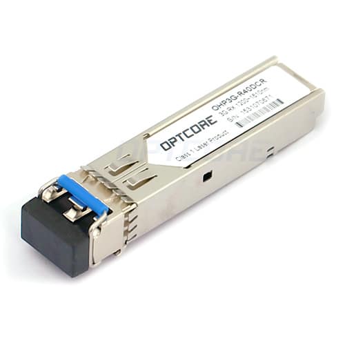
Fiber module card

  The Gigabit series fiber-optic module card is used with the switch and uses fiber or Category 5 twisted-pair cable to expand the LAN range and expand the bandwidth. It is suitable for large and medium-sized LANs to expand bandwidth and expand their network coverage. The fiber optic module is fully compliant with the IEEE802.3z protocol and operates in the 850nm and 1300nm modes. It is also fully compliant with the IEEE802.3ab protocol. It is compatible with other devices with the same Gigabit protocol. Due to its small size, it is directly installed inside the switch and requires no additional space. Powered by the switch, it is easy to install and use, and can be used with a variety of switches.

Fiber

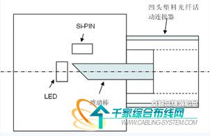
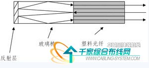
Coupler Fiber Coupler (Splitter) is a component that splits optical signals from one fiber into multiple fibers. It belongs to the field of optical passive components, in telecommunication networks, cable TV networks, and users. It is applied in the loop system and the regional network, and the largest item is used in the passive component of the fiber connector. The fiber coupler can be divided into a standard coupler (double branch, unit 1 × 2, that is, the optical signal is divided into two powers), a star/tree coupler, and a wavelength multiplexer (WDM, if the wavelength is high density, that is, the wavelength spacing is narrow, it belongs to DWDM), and the production method includes three types of sintering (Fuse), micro-optics (Micro-Optics), an optical waveguide (Wave Guide), while the production by sintering method is the majority (about 90). %).
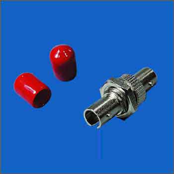
ST coupler

  FC coupler

Six-port SC coupler board

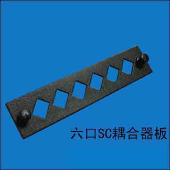
  The above products are suitable for transfer between test equipment, local area network, fiber optic CATV and different types of signs.

Single and multimode fiber converter

single and multimode fiber transceivers are used for data communication between optical cables, allowing users to expand the scale of UTP networks using single mode or multimode fiber, and are widely used in Ethernet data communication to extend the transmission distance. The expansion and extension of the network are achieved through fiber optic links.
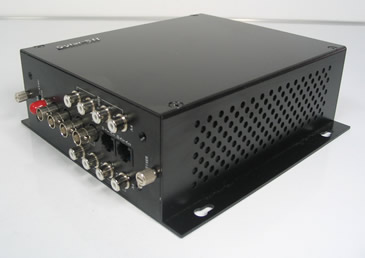
  Optical transceiver

video multiplexer adopts the most advanced digital video, high-speed transmission technology of Gigabit fiber and all-digital uncompressed technology, so it can support any high-resolution motion and still image without distortion transmission; overcome the conventional analog frequency modulation and phase modulation. The amplitude modulation of the multi-channel signal of the amplitude modulation optical transceiver is severe, the interference is serious, the transmission quality is inferior, and the long-term working stability is poor. It can also provide multiple channels of video, audio, data, telephone voice, and Ethernet transmission on the optical fiber at the same time, which greatly saves the investment cost of the user equipment and improves the utilization of the optical cable. Widely used in security monitoring, highways, electronic police, automation, intelligent community, customs, electricity, water conservancy, petroleum, chemical, and many other fields.

  The fiber distribution frame

fiber distribution equipment is designed for the fiber-optic communication equipment room. It consists of a fiber distribution unit and a cabinet or rack. The maximum wiring capacity of each unit is 24 fiber. The unit structure is 19-inch chassis, and the height is generally 9cm. In a standard cabinet or rack. Users can choose the number of units or unit specifications according to actual needs. It can be used as fiber distribution, and can also be used as a cable terminal box; it can be separately assembled into a fiber distribution frame, or it can be integrated with a digital distribution unit and an audio distribution unit in a cabinet/frame to form integrated wiring. frame. The device is flexible in configuration, easy to install and use, easy to maintain, and easy to manage. It is one of the indispensable devices for small and medium-sized fiber-optic communication equipment rooms to realize fiber-optic, fiber-optic, frit, and fiber-optic cable access. Applicable to the fiber termination point in the fiber access network, with the wiring and welding function of the optical cable, which can realize flexible jumper and storage of the optical fiber core.
The above equipment for the fiber access network greatly improves the data transmission and processing capability of the fiber access network, and can bring two advantages:

First, the problem of remote transmission of the access line is solved, and the fiber access network is provided. The coverage is broader. In this way, the number of transit nodes of the entire overlay network can be reduced, and the structure of the network is made simpler.

Second, it can meet the needs of users for a variety of new broadband services and can improve the quality of new business data. This solves the “bottleneck” problem of the traditional copper access network from the core technology and lays the foundation for the realization of the “fiber to the home” dream.

Therefore, the future fiber access network should become the main force of the Internet information highway.

Original Article Source https://www.mscbsc.com/viewnews-39311.html

Posted on Leave a comment

Talking about the testing and troubleshooting equipment of optical fiber network

In recent years, as people’s requirements for broadband speed are getting higher and higher because the performance of optical fiber is superior to that of copper cable, it is widely used in the backbone construction of broadband projects. At the same time, due to the increasing coverage of optical fibers, the detection of optical fiber faults is becoming more and more important. What methods can be used to eliminate the failure of optical components?

First of all, to eliminate the failure of optical components, it is necessary to pass the test, then what are the test and measurement equipment of the optical network? At present, the super six network cable manufacturers Weikang understand that there are mainly three kinds of instruments. They are optical loss test equipment (also known as an optical multimeter or optical power meter), fault locator (fault tracker), and fiber identifier.

1. Optical loss test equipment (combined by optical multimeter and optical power meter)

Optical power meter: Used to measure absolute optical power or relative loss of optical power through a length of the fiber. Optical Multimeter: Used to measure the optical power loss of a fiber link.

In order to measure the loss of a cable link, it is necessary to transmit calibrated steady light at one end and read the output power at the receiving end. These two devices constitute an optical loss tester. When combining a light source and a power meter into a set of instruments, it is often referred to as an optical loss tester (also known as an optical multimeter). When we measure the loss of a link, one person needs to operate the test light source at the transmitting end and the other person uses the optical power meter to measure at the receiving end so that only the loss value in one direction can be obtained.

Usually, we need to measure the loss in both directions (because there is a loss of the connection or it is due to the asymmetry of the transmission loss of the cable). At this point, the technicians must exchange equipment and conduct measurements in the other direction. However, what should they do when they are separated by more than a dozen floors or tens of kilometers? Obviously, if each of these two people has a light source and an optical power meter, then they can measure simultaneously on both sides. Today’s advanced cable test kits for certification testing are capable of two-way dual-wavelength testing, such as Fluke’s CertiFiber and DSP cable test series FTA cable test kits.

2, fiber fault locator (fault tracker)

Fault locators are mostly hand-held instruments for multimode and single-mode fiber systems. The OTDR (Optical Time Domain Reflectometry) technology is used to locate the fault of the fiber, and the test distance is mostly within 20 km. The instrument directly displays the distance to the point of failure by number. Suitable for: Wide Area Network (WAN), 20 km range communication systems, fiber to the roadside (FTTC), single mode and multimode fiber optic cable installation and maintenance, and military systems. In single-mode and multi-mode cable systems, fault locators are an excellent tool for locating faulty connectors and bad splices. The fault locator is easy to operate and can detect up to 7 multiple events with single button operation.

This device is based on the laser diode visible light (red light) source. When light is injected into the fiber, if there is a fiber failure, connector failure, excessive bending, poor welding quality, etc., the light emitted through the fiber can be on the fiber. The fault is visually located. The visual fault locator is transmitted in continuous wave (CW) or pulsed mode. Typical frequencies are 1 Hz or 2 Hz, but can also operate in the kHz range. Typical output power is 0dBm (1Mw) or less, the working distance is 2 to 5km, and supports all common connectors.

3, fiber recognizer

It is a very sensitive photodetector. When you bend a fiber, some of the light is radiated from the core. The light is detected by the fiber identifier, and the technician can identify the single fiber in the multi-core cable or the patch panel from other fibers based on the light. The fiber identifier can detect the state and direction of light without affecting transmission. In order to make this work easier, the test signal is usually modulated at the transmitting end to 270 Hz, 1000 Hz or 2000 Hz and injected into a specific fiber. Most fiber identifiers are used for single mode fiber optic cables operating at 1310 nm or 1550 nm. The best fiber identifiers are available to identify the direction and power of transmission in fiber optic cables and test cables online using technology.

In summary, the project that generally uses a large number of large-scale project equipment fiber optic is. To complete an optical loss measurement or to eliminate the failure of a fiber optic equipment, a calibrated light source, and a standard optical power meter are not available. Lack of.

Responsible Editor: DJ Editor

Original Article Source http://www.jifang360.com/news/2016120/n923777329.html

Posted on Leave a comment

Optical fiber communication: the characteristics of intelligent optical network

Since ASON (Intelligent Optical Network) is built on various transmission technologies, that is, an independent control plane is added on the transmission plane SDH and the Optical Transport Network (OTN), it supports various types of transmission networks currently available. Services for rate and different signal characteristics (such as format, bit rate, etc.). The ASON network can provide a fixed bandwidth transmission channel between two client network elements, the channel being defined between the input access point and the output access point of the optical network.

According to the transmission mode of light in the optical fiber, it can be divided into single mode fiber and multimode fiber.

The ASON business has the following aspects:

SDH service, supporting SDH connection particles VC-n and VC-n-Xv defined by G.707;

OTN service, supporting OTN connection particles ODUk and ODUk-n-Xv defined by G.709;

Transparent or opaque optical wavelength service;

10Mb/s, 100Mb/s, 1Gb/s and 10Gb/s Ethernet services;

Storage Area Network (SAN) services based on Fiber Optic Connection (FICON), Enterprise System Connectivity (ESCON), and Fibre Channel (FC).

ASON is scalable to new business types.

ASON can support multiple types of business models, each with its own business attributes, target market, and business management needs.

Business connection topology type

To support enhanced services (such as bandwidth on demand allocation, diversity circuit assignments, and bundled connections, etc.), ASON should support the separation of call and connection control. The separation of call and connection control can reduce excessive call control information for intermediate connection control nodes, eliminating the heavy burden of decoding and interpreting messages. The connection topology types supported by ASON include bidirectional point-to-point connections, unidirectional point-to-point connections, and unidirectional point-to-multipoint connections.

Since the call and the connection are separated, one call can correspond to multiple connections, and the current two-way point-to-point connection is the most important connection.

Business connection type

The ASON network supports three types of service network connections: permanent connection (PC), switched connection (SC), and soft permanent connection (SPC).

Both PC and SPC connections are managed by the management plane. The difference between PC and SPC is whether the connection is established in the optical network by using network management commands or real-time signaling. These two methods are service connections initiated by the operator.

The SC connection is initiated by the UNI signaling interface, and the service request of the user is sent to the operator through the UNI of the control plane (including the signaling proxy), that is, the user directly initiates the establishment of the service connection.

Business level

The current transmission network cannot formulate a corresponding tariff policy according to the service level, which causes waste of resource allocation, and the ASON network can conveniently divide the priority of the service circuit to provide a transmission service circuit with a service quality agreement (SLA). Customers have different requirements for the reliability of different connections. These requirements can be expressed in terms of “service level”. In an ASON network, the service level is mainly achieved by mapping to different recovery, protection options, and priority of related connections, such as establishing priority, maintaining priority (whether it can be pre-idle), and restoring priority.

The establishment of the priority mainly refers to the establishment response time of the service, which is to establish a service connection in the day, hour or minute.

Maintaining the priority (whether it can be pre-idle) mainly refers to whether the system will be idle to carry more important services in the event of other system failures, and the service connection itself has no protection.

Recovery priority is the recovery time and recovery level (such as the percentage of recovered services) in the event of a system failure.

Mapping a single business class to a range of protection and recovery options, each with a different choice. The control plane supports setting based on the priority of each link and supports bandwidth resource reservation as a recovery purpose and normalization of the failed repair route. Commonly supported service connection levels include: dedicated connections (1+1 and 1:1), shared protection (1: N and M: N), unprotected (transmitted on the primary circuit), unprotected services (in the protection circuit) On the transfer) and so on.

Service access method

In order to connect the service to the ASON network, the user first needs to establish a physical connection with the carrier network on the transport plane. According to the location of the carrier network and the customer, the service access can take intra-office access (the optical network element and the client network element are in one place), the direct remote access (with a dedicated link to the user end), and the connection Remote access to the subnet and dual-homing access.

ASON must support dual-homing access. Multiple addresses should not be required for dual-homing access for the same client device. Dual-homing access is a special case of access. The main purpose of adopting dual-homing access is to enhance the survivability of the network. When access fails, the customer’s service can rely on other access without interruption. Client devices can access the core network/operator in a dual-homed manner (two different paths).

From a security perspective, network resources should avoid unauthorized access. Service access control is a mechanism that restricts and controls the entity’s attempts to access network resources, especially through the UNI and external network node interfaces (E-NNI).

The Connection Admission Control (CAC) feature should support the following security features.

1. CAC applies to all entities accessing network resources through UNI (or E-NNI). The CAC includes an entity authentication function to prevent an imposter from fraudulently using network resources by pretending another entity. An authenticated entity will be given a service access level based on configurable policy management.

2. Mechanisms should be provided on the UNI and Network Node Interface (NNI) to ensure client authentication and link information integrity, such as link setup, teardown, and signaling information, for connection management and to prevent service intrusion. The UNI and E-NNI should also include CAC-based application charging information to prevent forgery of connection management information.

3. Each entity can utilize network resources through the authorization of the operator management policy.


Original Article Source https://www.mscbsc.com/viewnews-77189.html

Posted on Leave a comment

Introduction to 100G QSFP28 DAC Cable


       From providing flawless, high-flow media to real-time connectivity with customers around the world, today’s data centers require ultra-high speed. In order to provide a low-cost solution for data centers to connect switches, Ethernet switch vendors need to maximize the density of optical transceiver ports on their devices. This allows them to provide the maximum number of channels and the lowest cost per bit of traffic. The lowest cost of connecting 100G traffic is to use the 100G QSFP28 DAC Cable.

What is QSFP28 DAC?

QSFP28 DAC stands for 100G QSFP28 direct attach copper cable. 100G QSFP28 DAC is also called 100G QSFP DAC or 100G QSFP+ Copper Cable.
It is compliant with 100G Ethernet (100GBASE-CR4) specifications. So sometimes it is called 100GBASE-CR4 QSFP Cable. It contains four high-speed copper pairs, each operating at data rates of up to 25GbE. So the QSFP28 DAC cable assembly is suitable for power-efficient connectivity for short distance interconnects, such as data center, networking, and high-performance computing application.

What Is 100GBASE-CR4?

100GBASE-CR4 is one of the 100G Ethernet interface types. It is a standard of 100GBASE-R encoding and Clause 91 RS‑FEC over four lanes of shielded twin-axial copper cabling. It is defined as 4 x 25 Gb/s over copper cable per IEEE P802.3bj. 100GBASE-CR4 is different from 100BASE-KR4 that achieve 4 x 25 GB/s over the backplane. 100G QSFP28 DAC is 100GABSE-CR4 Cable that supports a max length of 5 meters.

QSFP28 DAC Types

QSFP28 DAC cable is available in two main types, QSFP28 direct attach a cable and QSFP28 breakout copper cable.

TypesLengthConnectorDatarate
QSFP28 direct attach cable1M~5MQSFP28100Gb/s
QSFP28 to 4 SFP28 breakout cable1M~5MQSFP28-SFP28100Gb/s for QSFP28, 25Gb/s for SFP28
  • 100G QSFP28 DAC Cable

Fig 1. 100G QSFP28 to SFP28 Breakout Cable & 100G QSFP28 DAC

What is the difference between QSFP28 DAC and 100G QSFP DAC?

In fact, they are the same. Sometimes QSFP28 DAC is also called 100G QSFP DAC or 100G QSFP+ DAC. The “QSFP” form factor was originally defined for <10G speeds. When it was adopted for 40G, the name became QSFP+ to denote the higher aggregate performance. The same “QSFP” form factor was later adopted for 100G but the electrical interface had to be upgraded to handle 25Gbps/lane. The electrical interface for 100G can handle up to 28Gbps, hence the engineering and industry name is QSFP28.

In Conclusion

100G QSFP28 DACs delivers aggregate data bandwidth up to 100 Gbps (4x 25 Gbps) with passive copper assemblies. They provide an ideal solution that allows 100G switches and routers to be used within the data center, with low power consumption and a maximum port count. As a pioneer in 100G QSFP DAC, OPTCORE manufactures a wide line of 100G copper cables with high quality and very competitive pricing. We are ready to be one of a reliable vendor for data center player.

Original Article Source https://www.optcore.net/archive25997/

Posted on Leave a comment

Short-distance plastic optical fiber communication system

Compared with cables, optical fibers have many advantages as transmission media. However, quartz fiber for common communication is difficult to connect, expensive, and expensive to install and maintain, and cannot be widely used for short-distance data communication or desktop data connection. Plastic optical fiber not only has the advantages of optical fiber but also has a diameter of generally 0.3 to 3 mm. The large diameter is suitable for connection, and the coupling efficiency of light is also high. At the same time, it is also soft, bending resistant, shock resistant, radiation resistant, and inexpensive. Convenient construction and other advantages can replace the traditional quartz fiber and copper cable to a certain extent. Therefore, the plastic optical fiber communication system is very suitable for short-distance (100m or so), medium and small capacity (several Kb/s to 100Mb/s), low-cost (tens of dollars) desktop data connection, and data between devices and device internal bus. connection.

Advantages of plastic optical fiber transmission systems After replacing cable connections with plastic optical fiber communication systems, the performance of the equipment will be improved in the following aspects.

● Improve the equipment’s ability to resist electromagnetic interference and nuclear radiation.

● No crosstalk. Optical cables are used to transmit signals without crosstalk between the signals.

● Lighten the weight of the system. The weight of a 1500m diameter 1mm plastic fiber is less than 2kg.

● Strong anti-lightning ability. The metal-free cable itself is a good insulator, and even if it is exposed to the outside, it will not cause lightning to damage the equipment.

System Description of Plastic Optical Fiber Communication The basic components of a plastic optical fiber communication system is: optical transmitters, optical receivers, plastic optical fibers, and some passive components. An optical transmitter converts an electrical signal (such as a TTL level signal) into an optical signal that is coupled into a plastic optical fiber and transmitted through a plastic optical fiber to an optical receiver that reduces the optical signal to an electrical signal (eg, TTL) Level signal).

The plastic optical fiber communication system focuses on short-distance communication, low cost, simple operation, and high reliability, so it is completely different from the quartz optical fiber communication system in the realization of the specific system.

    Plastic optical fiber communication transceiver

The plastic optical fiber transceiver is the core part of the plastic optical fiber communication system, including the optical transmitter and the optical receiver.

1 is a schematic diagram of the structure of an optical transmitter. The light-emitting diode (LED) is a high-brightness surface mount light-emitting diode for common display and has a driving current of less than 20 mA and a center wavelength of 590 nm (orange light). The reason why the 590nm LED is chosen is because the LED of this wavelength is very cheap, and the loss value of the plastic fiber is relatively low at the wavelength of 590 nm. The size of the LED chip is about 1.0mm×1.0mm, which is equivalent to the diameter of the plastic fiber, and it is easy to couple the optical signal into the plastic fiber.

Figure 1 is a schematic diagram of the structure of an optical transmitter

  The external input TTL level signal is FSK frequency modulated, and the TTL level signal is converted into a carrier signal more suitable for plastic optical fiber transmission to drive the LED illumination. The light signal from the light-emitting diode (LED) is directly coupled into a glass rod of 1.0 mm diameter, which is then coupled into a plastic optical fiber having a diameter of 1.0 mm through a glass rod.

2 is a schematic diagram of the structure of the optical receiver. The photodetector detects the optical signal and generates an induced current, and then is amplified by the amplification module in two stages, and is input to the FSK demodulation module to be demodulated by the flip-flop. The demodulated signal still contains high-frequency interference, which is filtered by the filter module and then judged by the decision module to be restored to the input TTL signal.

Figure 2 Schematic diagram of the optical receiver structure

  Both of these plastic fiber optic transceiver solutions are targeted for point-to-point connections. The transceiver of the bus type plastic optical fiber communication system should be a bus type. In the photoelectric conversion, the bus type plastic optical fiber communication transceiver and the point-to-point type plastic optical fiber communication transceiver are the same, but the bus type plastic optical fiber communication transceiver is half duplex. In the mode of operation, it has only one optical signal input/output port, or it has only one concave plastic optical fiber movable connector. At this time, the glass rod of the concave plastic optical fiber movable connector is connected with the LED and the Si-PIN. The end face is not a vertical way, but a 45° bevel, so that the beam can be split into two, one way to Si-PIN, all the way to the LED. Figure 3 is a schematic diagram of a bus type of plastic optical fiber communication transceiver.

Figure 3 bus type plastic optical fiber communication transceiver

    Plastic fiber optic patch cord

Plastic fiber optic patch cords are used to connect plastic fiber optic transceivers to plastic fiber optics by coupling optical signals into plastic fibers. Similar to cable connectors, it is divided into two types: concave head and convex head. The recessed plastic optical fiber active connector and the plastic optical fiber communication transceiver are integrated, and the male plastic optical fiber connector is connected to the plastic optical fiber.

The mechanical structure of the plastic optical fiber movable connector can be variously selected. Because the diameter of the plastic optical fiber core is large, the plastic optical fiber movable connector and the currently used quartz optical fiber movable connector can be completely different, and can follow the structure of the current cable connector ( Such as SMA structure), not only the connection loss is small, but also the use of wire clamps and electrician blades, it is convenient to complete the assembly of plastic optical fiber movable connector parts in the field.

    Plastic optical fiber fixed connector

Plastic fiber optic fixed connectors are used for the connection of plastic and plastic fibers. Using a V-groove structure, two plastic optical fibers are placed in a V-shaped groove, and the plastic optical fiber is fixed by a metal material, and then a heat-shrinkable sleeve is packaged to complete the fabrication of a plastic optical fiber fixed connector. The V-groove structure can achieve the purpose of quickly and easily making a plastic optical fiber fixed connector, and the connection loss is not large due to the large diameter (1 mm) of the plastic optical fiber.

   Plastic optical bus branch

Plastic fiber optic bus splitters are used in bus-type plastic fiber optic communication systems. As shown in Fig. 4, the optical input signal of any one port is evenly distributed to other ports after being totally reflected by the glass rod and reflected by the end face of the glass rod. The requirement for the plastic optical fiber bus splitter is that the additional loss is low, the second is that the uniformity of each port is good, and the third is that the structure is simple and the cost is low.

Figure 4 plastic optical fiber bus splitter

    Plastic fiber optic light multimeter

The plastic optical fiber multimeter consists of a light source, an optical power meter, a microprocessor, and a liquid crystal display. The LED is used as the light source and the Si-PIN is used as the detector. It is similar to the fiber optic multimeter currently in use, except that the wavelength range of light used is different and the cost is different.

Key Technology Low-Cost Plastic Optical Fiber Communication Transceivers Plastic optical fiber communication transceivers should be high-sensitivity, bursty receivers and extremely low-cost fiber optic transceivers. The principle of the plastic optical fiber communication transceiver is relatively simple, but requires the circuit cost to be extremely low, and also ensures high receiving sensitivity, high reliability, and small size. At present, the system has realized the transmission sensitivity of the transmitting end -10dBm, and the receiving sensitivity of the receiving end is -40dBm (10E-9 error rate).

    Plastic fiber optic patch cord

The key technology of the plastic fiber optic patch cord is that it is simple to manufacture and low in cost. It can be easily assembled on site by using simple tools such as wire clamps and electrician blades. Its connection loss is less than 1dB.

Plastic Optical Fiber Bus Splitter The plastic optical fiber bus splitter is a key component for implementing a bus-type plastic optical fiber communication system. The optical input signal of any one port is evenly distributed to other ports.

It seems to be the 1×N optical splitter that is commonly used nowadays. In fact, the principle and function are different. A 1×N optical splitter distributes the optical input signal of one port evenly to other ports or concentrates the optical input signals of N ports onto one port, and the plastic optical fiber bus splitter requires any port. The optical input signal is evenly distributed to other ports. It is a half-duplex device. In the normal operation of the bus-type plastic optical fiber communication system, only one port has an optical signal output, and the remaining ports are input optical signals. It is used in conjunction with a bus-type plastic optical transceiver to form a bus-type plastic optical fiber communication system. It not only requires a simple structure but also requires a low cost.

Original Article Source http://cabling.qianjia.com/html/2009-09/09_192636.html