Posted on Leave a comment

The importance of using fiber optic color codes in data centers

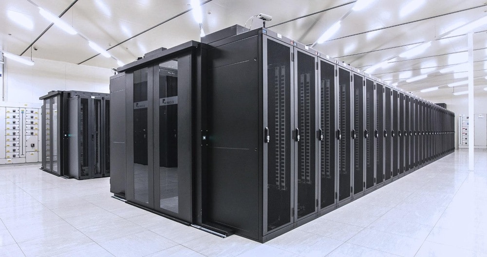
Using fiber optic color codes in the data center can effectively help technicians better manage fiber optic cables and reduce human error. Workers can easily obtain information about the device by viewing the cable color code, which simplifies the redundant inspection process. Making full use of the optical cable color coding system can save a lot of working time. The widely accepted color coding system and its important functions are described below.

  Introduction to Cable Color Code System

Fibers, bundles, and straps in fiber optic cables are often labeled with different color codes for easy identification. Many countries use this color code system. All of these systems are characterized by the use of 12 different colors to identify fibers that are gathered together in a common bundle, such as bundle tubes, drawstrings, yarn rolls, or other types of bundles.

Different countries and regions use different color code standards. For example, in Sweden, the S12 standard is used for micro cables and nanocables. The Type E standard is defined by Televerket and Ericsson used in Sweden. Countries such as Finland use the FIN2012 standard, but a color coding system generally accepted in the world, namely the TIA/EIA-598 standard.

TIA/EIA-598 color code specifications The following figure shows the cable color coding for the TIA/EIA-598 standard. If more than 12 fibers or bundles are to be distinguished, the color sequence is usually repeated on the fibers and bundles with ring marks or lines. As for the cable jacket, the orange, yellow, light green and black color scales are used for distinguishing.

The role of the cable color code in the data center

(1) Differentiating the cable grade

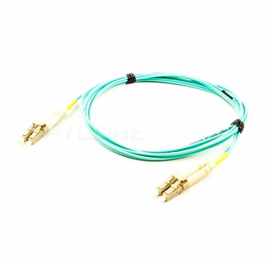
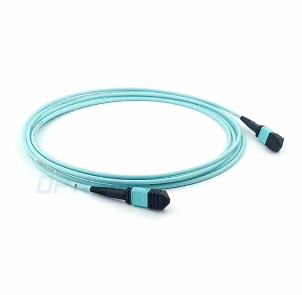
As mentioned above, the outer jacket color code can identify the cable grade. The OM1/OM2 cable is usually orange-sheathed, the OM3/OM4 cable is light green, the single-mode cable is yellow, and the hybrid cable (indoor/outdoor and outdoor cables) is black. One thing to note is that mixing OM1 and OM2 or OM3 and OM4 cables can be cumbersome to handle.

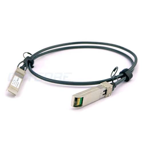
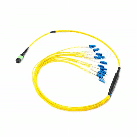
(2) Identify the fiber jumper

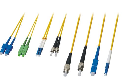
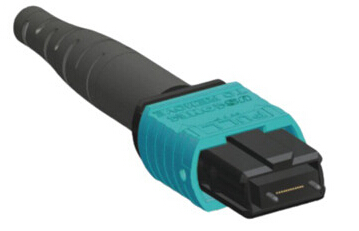
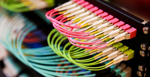
Marking fiber patch cords with color codes can reduce the possibility of human error. For example, a mission-critical jumper can be highlighted in red and the technician can be shown that the red jumper can only be moved with proper authorization or supervision. Again, the color of the fiber optic connector needs to be consistent with the fiber-level color standard, which will make it easier for technicians to use the correct connector on the fiber optic cable.

(3) Differentiating different ports

Color-coded port icons help identify different network routes based on internal requirements. Network management can be simplified by marking each patch panel port.

(4) Distinguishing Connector Sheaths

Staff can use color codes on the boot connectors to help technicians maintain proper parallel grouping of switch ports, making routine maintenance, movement, additions, and changes easier. If you change the connector color, you need to make sure that the cable color represents the fiber grade to avoid confusion. Workers can also change the color of the boot connector to differentiate between different deployments of the optical network, allowing technicians to easily view the contrast within the panel.

Conclusion

Visual management is more intuitive for experts who manage and maintain data centers. The fiber color code provides an ideal and easy way to solve fiber routing problems. Inside the cable, the fiber buffer can also be color coded in standard colors for easy connection and splicing. Therefore, if people are still plagued by problems such as fiber jumpers, it is a good idea to use fiber color code systems.

Edit: Harris

Original Article Source http://www.jifang360.com/news/2019412/n6592117478.html

Posted on Leave a comment

What is the difference between a video optical transceiver and a fiber optic transceiver?

Do you know the difference between video optical transceivers and optical transceivers? Today, Xiaobian introduces their specific differences from the following aspects. First, we must talk about the difference between video optical transceivers and optical transceivers from their concept.

The following are the differences between video optical transceivers and fiber optic transceivers:

1. The optical transceiver is mainly applied to the network, one end is connected to the optical fiber, and the other end is connected to the switch, mainly a network signal.

The optical transceiver can transmit video signals, 485 control signals, network signals, alarm signals, audio signals, switching quantities, and the like. The optical transceiver on the monitoring is generally: one end of the optical transmitter is connected to the camera, the other end is connected to the optical fiber, one end of the optical receiver is connected to the optical fiber, and the other end is connected to the display device.

2. The first talk about the optical transceiver, there are two conventional optical transceivers.

a. PDH optical transceiver for transmitting data signals.

b. The video optical transceiver is used to transmit video surveillance signals. The optical transceiver is a receiver (receiver and transmitter), that is, the main function of the video receiver is to convert the optical signal into an electrical signal (D/A). The main function of the transmitter, that is, the video transmitter, is to convert the electrical signal into an optical signal (A/D).

Fiber Transceiver

Earlier, the optical transceiver was used to transmit video signals. Then the fiber optic transceiver is used to transmit Ethernet signals. Although they are all photoelectric conversion, the protocols and principles of the electrical signals are different, and the signals transmitted on the optical path are also different.

3. One end of the optical transceiver is connected to the optical transmission system, and the other end (user end) comes out with a 10/100M Ethernet interface. Optical fiber transceivers are all used to achieve photoelectric signal conversion. The main principle of fiber optic transceivers is that fiber optic transceivers implemented by optocoupler usually have the following basic features.

a. Provide ultra-low latency data transmission.

b. Fully transparent to network protocols.

c. Use a dedicated ASIC chip to achieve data line-speed forwarding. The programmable ASIC combines multiple functions onto a single chip, which has the advantages of simple design, high reliability, and low power consumption, which enables the device to achieve higher performance and lower cost.

d. The equipment adopts 1+1 power supply design, supports ultra-wide power supply voltage, realizes power protection and automatic switching.

e. Support an ultra-wide operating temperature range.

f. Support full transmission distance (0 ~ 120 km)

The optical transceiver is a device that converts multiple E1 (a data transmission standard of a trunk line, usually at a rate of 2.048 Mbps, which is adopted in China and Europe) into an optical signal and transmits it. The price of the optical transceiver is different depending on the number of E1 ports transmitted. Generally, the smallest optical transceiver can transmit 4 E1s, and the largest optical transceiver can transmit 4032 E1s.

Optical transceivers are divided into three categories: PDH, SPDH, SDH.

PDH (Plesiochronous Digital Hierarchy) optical transceivers are small-capacity optical transceivers, which are generally used in pairs, also called point-to-point applications. The capacity is generally 4E1, 8E1, and 16E1.

The SDH (Synchronous Digital Hierarchy) optical transceiver has a large capacity, generally 16E1 to 4032E1.

SPDH (Synchronous Plesiochronous Digital Hierarchy) optical transceiver, between PDH and SDH. SPDH is a PDH transmission system with SDH (Synchronous Digital Series) features (based on the principle of code rate adjustment of PDH, and at the same time adopts some networking technologies in SDH).

Original Article Source  http://bbs.elecfans.com/jishu_1142152_1_1.html

Posted on Leave a comment

Optical Fiber Types

There are two classes of Optical Fiber:
Single-Mode Fiber: generally called SMF, it is used for long distance communication
Multi-Mode Fiber: generally called MMF, it is used for short distances less than 500 meters
The advantage of MMF is that it is cheaper than SMF, and multimode connectors are cheaper and easier to terminate reliably in the field.

In recent years, there are new optical cables called active optical cables (AOC). These have the optical electronics already connected, eliminating the connectors between the cable and the optical transceiver. They will plug into standard optical transceiver sockets. Because of the manufacturer can match the electronics to the required length and type of cable, the cost of these new active optical cables is lower than other optical solutions, therefore more and more applications are deployed.

There are different types of fiber optic fiber depending on the type of network and transfer distances:
10GBASE-SR – a port type for short range multimode fiber that covers the following distances based on the grade of optical fiber cabling:
FDDI -62.5 microns, reach of approximately 26 meters
OM1 62.5 microns – a reach of approximately 33 meters
OM2 50 microns – a reach of approximately 82 meters
OM3 50 microns – a reach of approximately 300 meters
OM4 50 microns – a reach of approximately 400 meters
In fact, most of the implementations prefer to OM3 and OM4 for fiber optical cabling to longer transfer distance.
10GBASE-LR: a port type for long range single-mode fiber, supports the reach of approximately 10 kilometers (6.2 miles).
10GBASE-LRM: a port type for long range multi-mode fiber, supports distances up to approximately 220 meters.
10GBASE-ER: a port type for extended reach single-mode fiber, supports the reach of approximately 40km.
10GBASE-ZR: a port type for non-standard extended reach single-mode fiber, supports the reach of approximately 80km.
10GBASE-LX4: a port type for multimode fiber and single-mode fiber, supports reach of approximately 300 meters (980 ft) over FDDI-grade, OM1, OM2, and OM3 multi-mode cabling and 10 kilometers ( 6.2 miles ) over SMF.
SFP+ Direct Attach
Also known as 10G SFP+ Cu, 10GBase-CR, or 10GBase-CX1, SFP+, or 10GbE Cu SFP cables.

SFP+ Direct Attach Cable uses a copper 10GbE cable that comes as active or passive twin-ax cable assembly and connects directly into an SFP+ housing.

Active cables are copper cables that have a silicon chip to boost the performance of the cable. Without a chip, the cable is considered a ‘passive’ cable. Passive cables are more susceptible to degradation due to attenuation and crosstalk. This active boosting allows cables to be more compact, thinner, longer, and transmit data faster than their passive equivalents.

SFP+ Direct Attach Cable has a fixed-length cable, typically 3, 5 or 7m in length, and like 10GBASE-CX4, is low power, low cost and low latency with the added advantages of using less bulky cables and of having the small form factor of SFP+.

Passive = 1, 3, 5 Meters
Active = 7, 10,12,15 Meters

Original Article Source https://www.optcore.net/optical-fiber-types/

Posted on Leave a comment

OM5 fiber technology standard and data center application

       The ISO and TIA standardization organizations released the latest wiring standards ISO 11801 3rd and TIA-568.0-D in 2017. The new standard removes the traditional OM1, OM2 multimode fiber optic cable and adds OM5 broadband multimode fiber optic cable. ISO reduces the attenuation of OM5 cables from 3.5 dB/km for previous OM3, OM4 cables to 3.0 dB/km, and increases the bandwidth requirement at 953 nm.

  ISO/IEC JTC1SC25 WG3 new project ISO/IEC TR 11801-9908 has released the first draft of WD to study wiring guidelines for high-speed network applications on multimode fiber, 10/40/100/200/ The transmission distances of OM3, OM4, and OM5 multimode fibers under 400G duplex and parallel network applications were studied.

  OM5 multimode fiber supports more wavelength channels, so the direction is the same for SWDM4 with four wavelengths or BiDi with dual wavelength. Similar to BiDi for 40G links, SWDM transceivers only require a two-core LC duplex connection, except that SWDM operates on four different wavelengths between 850 nm and 940 nm, one of which is dedicated to The signal is transmitted and the other fiber is dedicated to receiving the signal.

  OM5 fiber supports both future 400G Ethernet, for higher speed 400G Ethernet applications such as 400G Base-SR4.2 (4 pairs of fiber 2 wavelengths, 50G PAM4 per channel) or 400G Base-SR4.4 (4 For 4 wavelengths of fiber, 25GNRZ for each channel, only 8 cores of OM5 fiber are required. Compared with the first generation of 400G Ethernet 400G Base-SR16 (16 pairs of fibers, each channel transmits 25Gbps), the required number of fibers is only For a quarter of traditional Ethernet, SR16 is a milestone in the development of multimode 400G technology, demonstrating the possibility of multimode technology supporting 400G. In the future 400G mass application market, 400 multimode applications based on 8-core MPO are expected.

  As the physical transmission medium of data communication, optical fiber provides support for network equipment. The promotion of OM5 fiber cannot be separated from the support of network equipment manufacturers.

  There are currently two technologies for transmitting high-speed networks with a small amount of fiber on the market: BiDi and SWDM4. From the perspective of the industry chain, OM5 multimode fiber and BiDi and SWDM4 equipment manufacturers form an industry alliance, but whether this ecosystem can mature depends on the shipment of these 40/100G network equipment and the large deployment of OM5 fiber. The OM5 multimode fiber test is identical to the traditional OM3, OM4 multimode fiber test equipment, and test procedures, and the user does not need to purchase additional test equipment.

  The data center needs to be upgraded to 200/400G or higher in the future. It will have to face many optical module types such as MSA. In the absence of an IEEE standard project, users also need to care about whether there is open and standardized multimode wavelength multiplexing. Technology has emerged, and low-cost VCSEL 100G technology cannot achieve breakthroughs and other issues. Regardless of whether a parallel transmission optical module or a duplex transmission optical module is used in the future, network cabling is an important network infrastructure of the data center. It can be determined that the data center cabling must be open, scalable and flexible to support A variety of network architecture applications.

  Responsible Editor: DJ Editor

Original Article Source http://www.jifang360.com/news/2019426/n8147118755.html

Posted on Leave a comment

The difference between MPO and MTP fiber connection standards

With the rapid development of data centers, applications such as cloud computing and cloud storage have gradually penetrated various industries, and the bandwidth requirements for network communication have also increased rapidly. High-speed, high-capacity, and high-bandwidth often require more space and higher costs. This long-term contradiction, MTP / MPO fiber wiring standard has become the best solution for high density and high bandwidth. There are two kinds of fiber optic connection systems, MTP and MPO, which are very similar in the market. They are compatible with each other to a certain extent, so what is the difference?

The difference between MPO and MTP fiber connection standards
  MPO (Multi-fiber Pull Off) is the first generation of shrapnel-type multi-core fiber optic connectors designed by NTT Communications Corporation of Japan. It is now the name of a multi-core connector produced by several companies. MTP, a brand registered by USConec, specifically refers to the unique type of MPO connector it produces.

  What is an MPO connector?

  MPO is the abbreviation for “multi-fiber pull off”. The ferrule of this connector has more than one core and is mechanically snapped into place.

  Nowadays, various manufacturers in the market have a variety of MPO designs. The performance and cost of different types of connected products are very different. Some products make their performance more outstanding. Some MPO connectors can match many different brands of products, but some do not. This compatibility depends on how close these connectors are to standard products. For a complete definition of the MPO connector, please refer to the implementation of IEC-61754-7 and EIA/TIA-604-5 (aka FOCIS 5).

  What is an MT ferrule?

  The MT is a mechanical docking transmission with a multi-core number (usually 12 cores). The performance of the connector is determined by the accuracy of the fiber alignment and whether the alignment accuracy is stable after the connection. Ultimately, this alignment accuracy is determined by the eccentricity and spacing of the fiber and the matching accuracy of the guide pin and fiber. The performance of any MPO connector can be improved if the deviation of the guide pin and the molding process can be reduced during the production process.

 What is an MTP? Fiber Connector?

  The MTP connector is a high-performance MPO connector with multiple innovative designs. The MTP fiber connector is enhanced in optical and mechanical performance compared to conventional MPO connectors. The MTP connector is fully compliant with the professional standards of all MPO connectors, including EIA/TIA-604-5 FOCIS 5 and IEC-61754-7.

  MPO-type connectors are industry-standard, interchangeable MTP connectors, which means that it is possible to replace MPO connectors with MTP connectors for better performance. Most of the MPO connectors that follow the old design have quite limited performance and do not provide the same high performance as MTP fiber connectors.

  Why is the MTP connector described as a high-performance MPO connector?

  The performance and usability of the specially designed MTP connector are improved compared to the MPO connector. This design feature of MTP is unique and patented. The main features are as follows:

  1. The outer frame of the MTP fiber optic connector can be easily removed.

  The MT ferrule design ensures performance without loss during rework and regrinds during production. Yin-positive can be flexibly changed even after assembly, and the ferrule can be over-interfered after assembly.

  2, MTP fiber optic connector floating ferrule can improve the transmission performance when mechanical docking. The two connectors can be allowed to maintain good physical contact with the mating ferrules under the influence of external forces.

  3. The elliptical guide pin (PIN) of the MTP fiber connector is made of stainless steel. The elliptical guide pin can improve the precision of the butt joint and reduce the wear of the guide hole so that the MTP fiber connector can maintain high-performance transmission more permanently.

  4. There is a metal clip in the MTP fiber connector to fix the push ring. Specific characteristics:

 Prevent the loss of the guide pin;

  Concentrating the pressure generated by the spring;

  Preventing the spring from touching the friction fiber during mechanical stretching to cause damage to the fiber;

  5. The spring design of the MTP fiber optic connector maximizes the band gap of the 12-core and multi-core ribbon applications to prevent fiber damage.

  6, MTP fiber optic connectors have at least four standard matching parts, can be adapted to different types of fiber optic cable, more practical, including:

  around the cable with a loose structure;

  a ribbon cable with an elliptical outer cover;

 Ribbon bare fiber;

  The ultra-short-tail connector is ideal for applications in tight spaces, reducing volume by 45%.

  Can the MT ferrule be cleaned in the usual way?

  The best way to clean the dust and oil on the MT ferrule that affects optical performance is to use an advanced dry cloth cleaning kit, such as NTT-AT OPTIPOP, which is simply because it involves only a single channel. When using the above cleaning components, the contaminants will be completely removed. On the contrary, the use of low-quality fabrics or cotton swabs can remove the contaminants on the surface of the fiber, but the dirt will still exist on the edge of the ferrule, and the ferrule end faces are easily worn, causing serious Data loss.

  The OPTIPOP series of cleaning components are designed for yin and yang fiber optic connectors and can also be used with single core ceramic ferrules. OPTIPOP cassette and card cleaners use a refillable cleaning cloth that can be used for a long time and is less expensive to clean than traditional cleaning methods.

  Responsible Editor: DJ Editor

Original Article Source http://www.jifang360.com/news/201562/n330268516.html

Posted on Leave a comment

10GBASE-T Cabling vs 10G SFP+ DAC, which one is better?

10GBASE-T vs SFP+ DAC

01
Mar

Some recent advances in information and data center technology are helping to drive demand for 10GbE architectures, including virtualization and server clustering, network convergence, and advanced storage architectures. The Internet is also a major factor, the new forms of Internet-based information delivery and the explosive growth of digital and social media content. For a variety of reasons, 10GbE has become a flexible unified data center architecture.

For 10Gb Ethernet (10GE) switches and NICs, SFP+ transceivers and DAC cables connected to them have been widely used. Compared with 10GBase-T, SFP+ DAC has certain advantages: lower delay, lower power consumption, lower cost, and the technology is now available and stable. 10GBase-T offers a range of different benefits – familiarity, longer reach, and use of structured cabling and patch panels. So, in the end, choose 10G SFP+ DAC or 10GBASE-T for network cabling? This article will discuss this topic.

There are three options for 10GbE interconnect for specific intended uses:

  1.  SFP+ DAC Cable: These connections are ideal for deployment of blade chassis or 10GbE in racks over short distances.
  2.  Fiber cabling: Fiber optic connections are ideal for high traffic aggregate areas such as network backbones.
  3. 10GBase-T: 10GBase-T cabling is the third choice for top-of-rack switches or end-of-row usage models.

About 10GBASE-T

In the early days of Ethernet, there were several PHY standards, including various forms of coaxial cable, but Ethernet was widely adopted only after running on twisted-pair cables and as a point-to-point rather than an unstructured loop. It is practical to connect an Ethernet cable to each desktop next to the telephone line and set all connections in a wire cabinet. The connector for a twisted pair is an RJ45 connector. When Ethernet speed increases to 100 Mbps and then increases to gigabit speed, the same method is still maintained. Although cable requirements continue to evolve to maintain 100-meter distance standards, the basic method of using twisted-pair and RJ45 connectors remains the de facto standard.

10GBase-T requires a newer Cat 7 or Cat 6A up to 100 meters but can work on shorter distance Cat 6, Cat 5E or Cat 5 cables. 10GBASE-T cabling is backward compatible with 1G ports and these ports will still be used for IPMI and other low bandwidth devices. You can get a 10GBASE-T switch and connect everything you have. Used with 10G SFP+ DAC, it is difficult to find two ports that are adequate for all 10G and 1G devices.

Comparing cost

The SFP+ DAC is a lower cost alternative to fiber, but it can only reach 10 meters. It requires the purchase of an adapter card and requires a new top of rack (ToR) switch topology. DAC Cables are much more expensive than structured copper channels and cannot be field terminated. This makes the DAC more expensive than 10GBASE-T. Many networks now have Cat 6 or Cat 6a cabling installed, so they are ready for 10GBase-T. Any existing fiber can be reused for 10GbE. The new Cat 6 or Cat 6a cable can be added at a lower cost than direct-attached dual-axis copper or fiber multi-mode connections. Finally, training and knowledge transfer costs can be reduced because IT personnel are already familiar with Ethernet technology and RJ-45 connectors. Because SFP+ DAC does not have the flexibility and longer distance of 10GBASE-T, it only applies to 10GbE short-distance cabling.

Comparing Latency

The 10GBase-T PHY standard uses block coding to enable data to pass through the cable without error. The block encoding requires reading the data block into the transmitter PHY, running a mathematical function on the data, and sending the encoded data over the link. The opposite happens at the receiving end. The standard specifies 2.6 microseconds for the transmit-receive pair, and the size of the data block indicates that the wait time cannot be improved by approximately 2.0 microseconds per link. The SFP+ DAC cable uses simpler electronics without the need for code blocks. Typical latency is about 300 nanoseconds per link.

By comparison, we find that SFP+ DAC provides lower latency, but 10GBASE-T and SFP+ fiber cabling provides higher latency

Comparing Distance

Use the latest Cat 6A or Cat 7 cable, 10GBase-T up to 100 meters. The standard has been designed to allow patch panels and jumper cables. The SFP+ DAC provides a maximum distance of 10 meters (about 33 feet) based on passive copper cable. There are no patch panels used with DACs.

Comparing Flexibility

SFP+ DAC is not backward-compatible with existing GbE switches and only used for 10GbE switch.

Where rose, 10GBASE-T SFP+ is backward compatible with existing 1 GbE networks. Therefore, 10GBASE-T cabling offers the most flexibility and the lowest cost media.

Conclusion

From the comparison, we know that both 10GBASE-T cabling and 10G SFP+ DAC have their own advantages. SFP+ copper cable cabling is more suitable for use in data centers application, 10GBASE-T cabling will be better for wiring closets because of its flexibility and cost.

Original Article Source https://www.optcore.net/10gbase-t-cabling-vs-10g-sfp-dac/

Posted on Leave a comment

Advantages of MPO/MTP cable in 5G data center

In the 2G/3G/4G era, mobile communications are mainly deployed in the form of voice and data services. With the coming of 5G, the advantages in transmission speed and delay have been greatly improved, enabling 5G to be launched in more aspects, such as VR/AR, autonomous driving, intelligent manufacturing, smart home, Internet of things, etc. field. In the 5G laying, the demand for fiber optic cable will also grow rapidly. Among them, the MPO/MTP cable with advantages has begun to gain more attention. This article will take a closer look at the advantages of MPO/MTP cables in 5G data centers.

 Seven advantages of applying MPO/MTP cables in the data center:

  1. Protection of the effectiveness and safety of the investment. Although the application of MPO/MTP cable provides high requirements for the integrator’s preliminary and actual site survey capabilities, it can also fully protect the investor’s control over the project and the right to use the product. To avoid material waste and risk of project investment.

  2. Economically applicable, in general, the MPO/MTP pre-end method does not add additional costs.

  3. Easy to operate, easy to install, save installation time, and plug and play. We can make a simple comparison, such as laying a 288-core fiber optic cable, 3 construction workers, 2 sets of equipment, using traditional fusion fiber method, laying about 2 hours, and the time required for the fusion fiber plus installation is about 8 Hours, a total of about 10 hours, and if the MPO/MTP pre-cast cable is used, the laying time is still 2 hours, but the installation time is greatly reduced, only about 45 minutes, which undoubtedly has a huge advantage in time cost.

  4. The MPO/MTP pre-cast cable is fully tested in the factory, and no other products are added during the installation process. The field test operation is simple.

  5. The fiber link protection is sufficient. No solder joints and bare fibers are exposed to the air, and there are no problems such as aging and joint breakage.

  6. Maintenance is convenient and safe. The mechanical performance of the MPO/MTP pre-end cable splitter is excellent, and the maintenance or operation process will not affect the normal use of the fiber.

  7. Re-installable and mobile, the splitter of the MPO/MTP pre-cable cable can be quickly inserted and removed and reinstalled as needed.

  Compared with ordinary fiber optic cable, the main features of MPO/MTP cable are high density and pre-formed end, and finally embodied in MPO/MTP multi-core connector. Throughout the development of the industry, fiber optic connectors have two distinct stages of development: the first phase is to save space and to the direction of miniaturization, fiber optic connectors have evolved from traditional FC, ST, SC to LC, MTRJ. The second phase is not only to save space but also to meet the requirements of multi-core use, fiber optic connectors evolved from LC, MTRJ to MU, MPO/MTP.

  With the rapid development of 5G, data center interconnection, fiber sensing, and next-generation fiber technology, ultra-large capacity, ultra-high-speed, ultra-long-haul optical transmission networks will become a must for 5G data center construction. Conditions, the dual advantages of MPO/MTP cable in terms of technology and cost are likely to become the mainstream way for operators to build 5G data centers in the future.

  Editor in charge: Erin

Original Article Source http://www.jifang360.com/news/2019112/n0724114897.html

Posted on Leave a comment

How to choose data center MPO/MTP high-density fiber pre-connection system?

Mobile communication network news, MPO/MTP high-density optical fiber pre-connection system is currently mainly used in three areas: high-density environment applications in data centers, fiber-to-building applications, optical transceivers in optical splitters, 40G, 100G SFP, SFP+, etc. Connection application inside the device. This article focuses on why data centers use MPO/MTP high-density fiber pre-connection systems and how to choose such high-density fiber pre-connection systems.

  Before introducing the current use of MPO/MTP high-density fiber pre-connection systems in these situations, it is necessary to make a brief introduction to MPO/MTP. In the field of communication and data transmission, the development of optical fiber connectors is far more developed than the development of copper connectors. According to incomplete statistics, so far, hundreds of fiber optic connectors have been developed, but there are more than a dozen that are actually used in a wide range. Throughout its development, fiber optic connectors have two distinct stages of development:

  The first stage: in order to save space and develop towards miniaturization, fiber optic connectors have evolved from traditional FC, ST, SC to LC, MTRJ, E2000

  The second stage: not only to save space but also to meet the requirements of multi-core use, fiber optic connectors evolved from LC, MTRJ, E2000 to MU, MTP/MPOFIBER CABLING, now an MTP/MPO multi-core connector can meet 2 cores, 4 cores , 8-core, 12-core, 24-core, currently up to 72 cores.

  The benefits of this development in the second phase are obvious. Look at the 40G and 100G requirements for fiber-optic network transmission specifications. Multi-core transmission, that is, 8-core or 20-core. In this way, MPO/MTP FIBER CABLING can meet the requirements of high-speed network applications in a small space. However, engineers who work on the site also bring great challenges and even impossible tasks. Of course, there is now a good alternative, which is the pre-connected system of the manufacturing plant.

  The application of the MPO/MTP fiber pre-connection system in the data center has also been a matter of the past few years, and it is also the most important application of the MPO/MTP pre-connection system in China. The reason is not as noble as imagined, but it is actually an inevitable choice. Let me talk about the first reason: the data center space is always not enough. Just like the completion of Beijing’s subway for half a year, passenger traffic is full. This is actually a contradiction between limited resources and unlimited demand. This phenomenon is manifested in various fields in China today. To solve the problem of insufficient space, you can increase the space or increase the utilization of space. It is unrealistic to increase space in a designed data center. Increasing the space utilization rate means increasing density. As the two major wiring systems in the data center: copper cables, cable cabling systems, in fact, copper systems can also use high density, but this high-density space savings are limited. Because it is not only impossible to find a balance between the high frequency and the larger line; the electrical transmission performance of the cable at high frequency is not easy to meet, and the high-frequency electronic signal is also transmitted in the multi-core copper transmission. A series of questions. Of course, in order to install a convenient copper pre-connection system on site, this is another topic, no matter here. Therefore, in order to get more transmission bandwidth in the same space, switching to optical cable transmission is an inevitable choice, but this does not mean that a high-density optical fiber pre-connection system is required.

Original Article Source  https://www.mscbsc.com/viewnews-94461.html

Posted on Leave a comment

How to organize the fiber jumpers in the cabinet

How to organize the fiber jumpers in the cabinet

1 Steps for skipping content:

The first step: identify the light and the room, find the splitter.

Step 2: Identify the splitter number.

Step 3: Find the splitter port configured on the work order.

Step 4: Find the port of the cable core of the access user.

Step 5: Jump from the splitter port to the user cable port.

2 Basic knowledge and specifications of fiber jumper:

1) The fiber-optic operation must meet the principles of ODF frame, light communication, tidy inside the integrated box, beautiful wiring, easy operation, and less space.

2) The length of the jumper must be within the range of 500mm.

3) Jumpers of insufficient length shall not be used. It is not allowed to use flanges to connect two jumpers.

4) Each jumper should ensure that the radius of curvature is greater than 400mm.

5) General requirements for fiber removal:

1 For the fiber on the upper line, the cable should be off the outside of the ODF frame. Select the most suitable fiber column for the remaining fiber volume, and move the fiber upwards on the inside of the ODF frame. The horizontal edge is on the lower edge of the ODM and is perpendicular to the corresponding terminal.

2 One jumper is only allowed to go up once in the ODF frame (along the outside of the ODF frame), once on the side (along the inside of the ODF frame), and take a fiber column. It is forbidden to entangle, cross and hang between the multiple fiber columns. That is, there must be no filament winding on the upper edge of each disc.

3 The specific situation of the site should be stipulated after the initial preparation of the jumper.

4 All jumpers must be placed in the ODF frame. It is strictly forbidden to deploy outside the aircraft and fly the line.

5 The super long jump fiber for emergency use shall be hung on the inner fiber disc according to the rules, and shall not affect the future fiber jump.

3 Jumper type and length control

1) Select the corresponding  SC-SCfiber jumper, FC-FCfiber jumper, SC-FCfiber jumper according to the flange head on the splitter and the splitter box.

2) The fiber jumper from the splitter to the user table, the length of the length is controlled within 50CM, and the pigtails of 1m, 2m, 2m5, 3m are generally selected.

3) The ONU and the fiber terminal jumper in the user terminal box generally use 50CM short pigtail.

4 Jumper label management and specification

1) All jumper labels must be labeled with the machine and no handwriting is allowed.

2) In the machine room, light communication, and corridor, the fiber-optic to the user’s leather cable must be attached to both ends of the fiber-optic cable.

3) The effect after completion is uniform specification length, according to the gap of the terminal position, the labels are not staggered.

4) The front side is the name of the light path, and the reverse side is the light path code and barcode, and the orientation is uniform.

5) The change text hangs down with the pigtails, naturally facing up.

5 Perform the necessary optical path test

After each fiber path jump is completed, it needs to be tested. The test steps are as follows:

1) Test the wavelength of the splitter at 1490 with an optical power meter, and the optical power should be less than -22dB.

2) The user end tests with the 1490 wavelength of the optical power meter. The receiving power should be less than -23dB, and the maximum sensitivity of the ONU is generally -24dB.

3) Use the ONU device to debug the Internet for the user.

4) If there is no light, you can judge whether the fiber is wrong by the visible light source (red light).

5) If there is no fiber but still no light, when the loss is large, the ONU can not work normally, and the cable maintenance department can be informed.

6 Resource Management

It is strictly forbidden to change the fiber order of the construction sheet without authorization. The optical path resources need to be changed during the loading and maintenance process. The relevant information of the optical path is recorded on the work order and timely reported to the resource department for updating.

The above are all the techniques for dust removal in the cabinet and how to organize the fiber jumper in the cabinet. In fact, the cabinet can be extended by cleaning, and the fiber jumper in the cabinet is arranged to facilitate our future inspection and aesthetic effect.

Disclaimer: All information indicated as other sources is transferred from other platforms, the purpose is to convey more information, does not represent the views and positions of this site. Please contact us if there is any infringement or objection.

Posted on Leave a comment

How does the switch choose the correct branch jumper?

       This article will serve as the best guide for MTP-to-LC branch jumpers for structured cabling applications, focusing on 12- and 8-core MTP-to-LC branch jumper cables for LAN and LAN switches from different vendors. Worker light port.

  What is the MTP-LC branch jumper?

  A branch jumper is a fiber optic cable assembly with a multi-core MTP connector on one end and an outer jacketed branch with a single or dual core LC connector on the other end. It provides a conversion for the backbone of the MTP connector, the backbone extension cable or the back of the single/dual connector module. Figure 1 shows an example of some differently constructed branch jumpers.

      What are the benefits of using the MTP-LC branch jumper?

  When designing a network system, it is very important to plan the structured cabling in advance. Our goal is to address the current network needs and adapt to future growth. Structured cabling systems have the flexibility to handle the usual execution moves, adding or changing infrastructure tasks, along with the evolution of the network. Using MTP-LC branch jumpers in high-density LAN or storage switches can help you improve structured cabling.

  Use the branch jumper component to compare some of the main advantages of traditional jumpers:

  1. Branch jumpers provide a clean, high-density approach to high-density switch port replication, which reduces the risk of port corruption or errors on the switch.

  2. The branch jumper occupies less space in the cabinet and has better vertical management than the traditional jumper. The branch at one end of the 12-core branch jumper is much smaller than the jumper with an equal number of cores.

  3. Reduce cable congestion for LANs and storage networks; improve airflow for increased cooling and make moving, adding and changing easier (mac).

  4. The branch jumper provides a network port that can be used to include an engineered interleaved LC branch to match the electronics to provide seamless integration between the cabling infrastructure and the electronic device.

  What is the typical application of the MTP-LC branch jumper?

  The MTP-LC branch jumper is used for port replication of the blade switchboard to facilitate connection of these ports to other devices. There are two types of branch jumpers, module branch jumpers, and trunk branch jumpers based on the specific application and which components are plugged in.

  The module branch jumpers are connected directly to the rear of the MTP-LC module, copying the switch ports to the patch panels located in the same or adjacent racks. When this application is typically used, the switch is in MDA or column header switching. Figure 2 depicts an example of a module branch jumper application.


  The switch-mapped patch panel is located outside of the switch’s location. Deploying this application is usually the main distribution area (MDA) required when you have a common switch area and port replication. Figure 3 depicts an example of a trunk branch jumper application.


  What LC branch length should I use for the MTP-LC branch jumper?

  The optimal branch jumper LC branch length will depend on the following factors: chassis model, blade type, number of blade ports, port direction, and routing. This article provides customized staggered branch jumpers for different industry vendors to match the ports of each of their data center switch product lines, providing seamless integration between cabling infrastructure and electronics.

  Staggered types 1, 2, 3, and 5 are precisely designed lengths that are specifically matched to the layout of switch ports at different vendors. In addition, this article provides a variety of uniform length/non-staggered branch lengths (eg, 6 inches (staggered type 4 branches), 12 inches, 24 inches, and 36 inches) depending on your wiring needs. Figures 4 and 5 show different staggered type configurations.


  Which direction of the MTP-LC branch jumper should I choose when wiring the switch?

  The best switch routing direction will depend on two factors, the direction of the blade board and the fan/intake position. For example, if your switch is a horizontal blade card and fan/air intake position, it does not prevent the branch jumper from coming left or right, which can be attributed to customer preferences. On the other hand, if the fan/intake is on one side of the switch, you should route your branch jumper from the other side.

  The same applies to switches in the vertical blade card. This article provides an optimal routing direction for different industry manufacturers based on different switch chassis products. Figure 6 shows the different routing directions.

  With the widespread availability of switches in the networking market, there are several configurations of MTP-LC branch jumpers to choose from. The rest of this document will help you decide which branch jumpers are best for your storage network or LAN switch cabling. On the next page are Tables 1 and 2, summarizing the use of 12-core or 8-core-based branch jumpers based on switch manufacturer, module, port number, port direction, and routing direction. The part numbers for each different branch jumper type are in Tables 3 and 4. The illustrated example is a different switch/blade-mounted MTP-LC branch jumper that can be found in Appendix A. 

Disclaimer: All information indicated as other sources is transferred from other platforms, the purpose is to convey more information, does not represent the views and positions of this site. Please contact us if there is any infringement or objection.