Posted on Leave a comment

What is the difference between shielded and unshielded jumpers?

There are many types of network cables. If you distinguish them according to the application scenario, you can divide them into outdoor and indoor network cables, shielded and unshielded network cables. Then, there will be many friends who will have doubts. What is the difference between shielded jumpers and unshielded jumpers? What is the role?

First, what is the difference between shielded jumpers and unshielded jumpers?

Shielded cable (shielded twisted pair), the outer layer of the shielded cable is wrapped in aluminum to reduce radiation but does not completely eliminate radiation. The price of the shielded cable is relatively high, and it is more difficult to install than the unshielded cable. Similar to coaxial cable, it must be equipped with a special connector that supports shielding and corresponding mounting technology. But it has a higher transmission rate and can reach 155Mbps within 100 meters. The price is relatively high and requires special connectors that support shielding and comparable mounting techniques, but at a higher transmission rate than the corresponding unshielded twisted pair.

The unshielded network cable is divided into 4 pairs by 8 differently colored wires. The effect of paired twisting is to minimize the influence of electromagnetic radiation and external electromagnetic interference. In the EIA/TIA-568 standard, twisted pairs are classified into three types: four types, four types, and five types of lines. The three most commonly used types in the network are the three types of lines and the five types of lines. Currently, there are more than six types.

Second, what is the role of shielded jumpers and unshielded jumpers?

The unshielded network cable is mainly used in the network without interference, so the shielded network cable is relatively used in an environment with interference. The unshielded network cable has no shielding layer. Its diameter is relatively small, and it is space-saving. It can be used in an environment without interference, which is not only convenient to use, but also saves space when wiring.

When indoors, our interference source is generally not very serious. The transmission speed of the unshielded network cable is actually faster than the shielded network cable. If the spatial structure of the wiring is close to the interference source of the air conditioner, the shielded network cable is used.

In terms of price, the price of the unshielded network cable is lower than the cost of the shielded network cable. Some people may ask, the transmission speed is obviously better than the unshielded network cable, why the price is low, but the price of the network cable is not completely determined by the transmission speed.

The shielded network cable exists in order to cope with the environment with interference sources, so its cost is relatively high, and it is also difficult to wire.

Therefore, the price of the unshielded network cable and the shielded network cable differs in this layer of shielding function, but not all shielded network cables are used in the electromagnetic environment. In fact, in the ordinary electromagnetic environment, we can use the unshielded network cable to deal with it. Normally, there will be no problem. According to the environment, the network cable can be used to make the wiring scheme better. Cost savings and easy wiring are the first priority.

In fact, the difference between a single shielded network cable and a double shielded network cable is that the double shielded network cable has a more shielding layer than the single shielded network cable. In fact, it can be seen from their names. And double-shielded cable transmission speed than a single shielded cable is slower.

Original Article Source http://www.qianjia.com/html/2019-04/10_332600.html

Posted on Leave a comment

What are the precautions for fiber jumper construction?

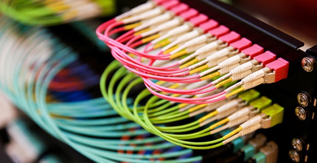
As we all know, the fiber jumper is used to make the jumper from the device to the fiber-optic wiring link. It has a thick protective layer, which is generally used for the connection between the optical transceiver and the terminal box. So you know how to make fiber jumpers? What are the precautions for fiber jumper construction?

How to make fiber jumpers

1 Steps for skipping content:

The first step: identify the light and the room, find the splitter.

Step 2: Identify the splitter number.

Step 3: Find the splitter port configured on the work order.

Step 4: Find the port of the cable core of the access user.

Step 5: Jump from the splitter port to the user cable port.

2 Basic knowledge and specifications of fiber jumper:

1) The fiber-optic operation must meet the principles of ODF frame, light communication, tidy inside the integrated box, beautiful wiring, easy operation, and less space.

2) The length of the jumper must be within the range of 500mm.

3) Jumpers of insufficient length shall not be used. It is not allowed to use flanges to connect two jumpers.

4) Each jumper should ensure that the radius of curvature is greater than 400mm.

5) General requirements for fiber removal:

1 For the fiber on the upper line, the cable should be off the outside of the ODF frame. Select the most suitable fiber column for the remaining fiber volume, and move the fiber upwards on the inside of the ODF frame. The horizontal edge is on the lower edge of the ODM and is perpendicular to the corresponding terminal.

2 One jumper is only allowed to go up once in the ODF frame (along the outside of the ODF frame), once on the side (along the inside of the ODF frame), and take a fiber column. It is forbidden to entangle, cross and hang between the multiple fiber columns. That is, there must be no filament winding on the upper edge of each disc.

3 The specific situation of the site should be stipulated after the initial preparation of the jumper.

4 All jumpers must be placed in the ODF frame. It is strictly forbidden to deploy outside the aircraft and fly the line.

5 The super long jump fiber for emergency use shall be hung on the inner fiber disc according to the rules, and shall not affect the future fiber jump.

3 Jumper type and length control

1) Select the corresponding fiber jumper (SC-SC, FC-FC, SC-FC) according to the flange head on the splitter and the splitter box.

2) The fiber jumper from the splitter to the user table, the length of the length is controlled within 50CM, and the pigtails of 1m, 2m, 2m5, 3m are generally selected.

3) The ONU and the fiber terminal jumper in the user terminal box generally use 50CM short pigtail.

4 Jumper label management and specification

1) All jumper labels must be labeled with the machine and no handwriting is allowed.

2) In the machine room, light communication, and corridor, the fiber-optic to the user’s leather cable must be attached to both ends of the fiber-optic cable.

3) The effect after completion is uniform specification length, according to the gap of the terminal position, the labels are not staggered.

4) The front side is the name of the light path, and the reverse side is the light path code and barcode, and the orientation is uniform.

5) The change text hangs down with the pigtails, naturally facing up.

5 Perform the necessary optical path test

After each fiber path jump is completed, it needs to be tested. The test steps are as follows:

1) Test the wavelength of the splitter at 1490 with an optical power meter, and the optical power should be less than -22dB.

2) The user end tests with the 1490 wavelength of the optical power meter. The receiving power should be less than -23dB, and the maximum sensitivity of the ONU is generally -24dB.

3) Use the ONU device to debug the Internet for the user.

4) If there is no light, you can judge whether the fiber is wrong by the visible light source (red light).

5) If there is no fiber but still no light, when the loss is large, the ONU can not work normally, and the cable maintenance department can be informed.

6 Resource Management

It is strictly forbidden to change the fiber order of the construction sheet without authorization. The optical path resources need to be changed during the loading and maintenance process. The relevant information of the optical path is recorded on the work order and timely reported to the resource department for updating.

What are the precautions for fiber jumper construction?

1 Types and uses of pigtails

According to the existing ODF shelf and device port standards, fiber jumpers can be classified into the following types:

(1) According to the interface type: the pigtail interface can be divided into three interfaces: FC, SC, and LC. The two ends are FC-FC, SC-SC, LC-LC, FC-SC, FC-LC, SC. -LC, a total of six types of fiber jumpers.

(2) According to the length of the interface: the pigtails are 1.5 meters, 2 meters, 3 meters, 5 meters, 10 meters, 15 meters, 20 meters. We usually use 3 meters, 5 meters, 10 meters, 15 meters, and 20 meters.

(3) Use: FC interface is used for ODF frame to connect remote core; SC interface is used for ODF frame (less) and equipment, such as OLT and ONU device interface in EPON, photoelectric converter interface, etc.; LC interface only Used on the interface of the device. Two of the three core interfaces are combined to achieve a physical connection between the ODF and the ODF shelf, between the ODF shelf to the device, and between the device and the device.

2 Preparations and precautions outside the field before fiber jumper:

Before the fiber jumper, it is generally based on the needs of the business, there will be a need for a fiber jumper. But for different needs, the equipment to be jumped is different, and the preparation work that needs to be done is different. Therefore, before the fiber jumper, there must be clear working ideas and clear work objectives. Otherwise, there will be cases where the jumper is not brought or not so that the work task cannot be completed on time, and the work target cannot be realized on time. , affecting the development of the company’s business. Therefore, preparation before the fiber jump is critical to the achievement of the work objectives. Preparations outside the site are generally outside the computer room, and the following preparations are required. Finally, there are matters needing attention.

1) Preparation work outside the field before fiber jumper:

1 Working ideas: What is the purpose of the jumper? What equipment is needed to jumper? What interface is the device? What type of fiber jumper do I need to use? Do I need to prepare an optical module? Do you need other tools? These are all things that need to be considered in advance.

2 Tool preparation: optical power meter (including test fiber jumper), red light pen, tube sleeve, label paper, oil pen, notepad, pliers, electric tape.

3 Material preparation: fiber jumper, optical module, the quantity, type or length of the corresponding material is determined according to requirements.

4 Disk information preparation: If the interconnection between different computer rooms, you need to know the information about the machine room and record it on the notebook.

2) Precautions before the field of fiber jumper:

1 If you need to bring a module, you should pay attention to the module type, distance, wavelength, and other parameters;

2 The core should pay attention to the type and length of the interface, and pay attention to whether it is necessary to cross the cabinet, how far apart the cabinet is, and whether it is necessary to walk the distribution frame.

3 Note that with spare modules and fiber jumpers, at least one spare module and one pair of corresponding jumpers must be prepared.

3 Preparations in the field before the fiber jumper

1 Untie the pigtail tape and unfold the two pigtails. After the whole fiber is unfolded, the same interface is put together. After straightening, the two fiber jumpers are bundled together with electric tape.

2 If you jump into the core of different computer rooms, you can first contact the colleagues in the remote computer room to test whether the pigtails can be used normally, whether the ODF shelf is faulty, and whether the cable light loss is normal; if it is the equipment in the machine room Connected, connected to relevant equipment, test whether the pigtail can be used normally;

3 Use Notepad to copy the serial number of the module to be used, the length and type of the core, to facilitate asset management.

4 Precautions in the field of fiber jumper

1 Jumping is divided into three cases: the same cabinet jumper, adjacent cabinet jumper, and cross-rack jumper. The difference is that the pigtails across the cabinet are protected by bushings when they cross the cabinet, and the patch panels are used for the patch panels.

2 When the pigtail is connected, connect one end of the core to the device, and the other end is routed from the left side facing the cabinet. The excess pigtails are wrapped in a circle (not folded into a straight line) and wrapped with electric tape. Well, connect the other end to the device or the ODF frame. The ODF frame enters the line from the left side hole of the ODF frame, and the flying line cannot appear.

After 3 good cores, label paper should be attached and labeled according to the naming requirements.

4 After the label is placed, the registration of the core of the ODF frame should be done. If the main core is jumped, the use of the core should be used (the local and the opposite information is written on the label paper). And use the notepad to record it.

5 Collect the protective caps of the module and pigtails and place them in the small box at the bottom of the cabinet for future use.

5 Finishing work after fiber jumper:

Before leaving the machine room:

1 Contact the relevant colleague to test whether the core is connected and whether the jump target has been completed;

2 After confirming that the fiber-hopping work is successfully completed, carry out on-site tool finishing, and clean the waste materials such as the pigtail packaging bag to keep the environment of the machine room clean and tidy;

3 Close the room lights, check again if something is in the machine room, and pay attention to lock the machine door when leaving.

The above is all the contents of the fiber jumper and the fiber jumper construction precautions. Of course, the fiber should not be excessively bent and looped during use, which will increase the attenuation of light during transmission. Be sure to protect the fiber connector with a protective sleeve after use. Dust and oil can damage the coupling of the fiber.

Original Article Source http://cabling.qianjia.com/html/2019-05/22_337862.html

Posted on Leave a comment

What is the video optical transceiver how to judge the performance index of the video optical transceiver

At present, multi-channel digital video optical transceivers on the market involve a wide variety of technical indicators. Most engineering companies and users lack the corresponding means to judge the rationality and authenticity of technical indicators, so it is easy to lose direction when selecting products. So, what is a video optical transceiver? How to judge the performance indicators of video optical transceivers?

What is a video optical transceiver?

The video optical transceiver is a device that converts one or more analog video signals into optical signals through optical fibers through various codes. Since the video signals are converted into optical signals, the two technologies of analog conversion and digital conversion are adopted. Therefore, video optical transceivers are divided into analog optical transceivers and digital optical transceivers. The principle of the optical transceiver is to modulate the signal onto the light and transmit the video through the optical fiber.

How to judge the performance index of video optical transceiver

1 Technical indicators considered

Multi-channel digital video optical transceivers can have a variety of functions, each type of function has corresponding technical indicators, such as video indicators, audio indicators, asynchronous data indicators, Ethernet indicators and so on. Specific technical indicators may require manufacturers to provide third-party test certificates. Conditional engineering companies should re-test according to the indicators provided by the manufacturers before purchasing equipment to verify the actual technical specifications of the equipment and the integrity of the manufacturers. Here we focus on the following two video indicators from an engineering perspective.

1.1 3dB video bandwidth is sufficient

Video bandwidth is a common problem. The video bandwidth is insufficient, the details of the monitor picture are not clear enough, the horizontal resolution is low, and even the color distortion or loss occurs. Because of the importance of video bandwidth to image quality, some unscrupulous vendors deliberately exaggerate the video bandwidth of their products to deceive customers.

A multi-channel digital video optical transceiver produced by a manufacturer claims that its video bandwidth is 8M, but its externally announced video sampling frequency is 12.5M. According to Nyquist’s law of sampling, to truly restore the signal, the sampling frequency should be at least twice the frequency of the signal.

In this way, the theoretical video bandwidth of this manufacturer’s optical transceiver may not exceed 6.25M in any case. Obviously, this is a lie that exaggerates performance to deceive customers, so that vendors without commercial reputation should not be considered for purchase. But not all customers can accurately identify the lie of the manufacturer. For the average engineer and user to observe the details of the image, the video bandwidth of the device can be roughly judged.

1.2 APL range is wide enough

APL, the average image level, is a measure of the average video brightness level and expressed as a percentage of the maximum white level. When APL is low, the image is dark, and when APL is high, the image is lit. Many engineers are not very concerned or not familiar with this indicator.

However, if there is a problem encountered in some projects: the video signal is transmitted through the optical transceiver, when there is a large area of ​​white in the picture (such as when the camera is illuminated by strong light), the picture on the monitor will horizontally jitter, then Engineers must be familiar. This is because the APL range of video optical transceivers produced by some manufacturers is too narrow. When there is a large area of ​​white in the image signal, the DC component in each line of image signals increases, and the APL will increase, causing the amplitude of the line sync signal to decrease. Or lost, the monitor cannot detect the line sync and the picture is shaken.

2 Reliability considerations

As a security monitoring project, the reliability of the equipment should be the first consideration. The reliability of the equipment must be considered by the equipment manufacturer when designing the product. However, some manufacturers may not be willing or do not know how to do this work for some reasons. The focus here is on the following issues from the engineering perspective.

2.1 Power supply is convenient, the power supply range is wide

The power supply is the primary consideration for ensuring the reliability of digital video optical transceivers. The power supply cannot be guaranteed to be reliable and reasonable. The reliability of digital video optical transceivers has become fishing in the water. The video optical transceiver with 220VAC power supply is convenient to take power and has high reliability. In the project, 220VAC power supply optical transceiver should be selected as much as possible. At present, the optical transceiver mainly has two power supply modes, one is a powerful external type, and the other is a powerful built-in type, that is, the power supply and the optical transceiver are integrated. From the perspective of engineering applications, the built-in power supply is not only easy to install, but also has high reliability. Therefore, most of the current multi-channel digital video optical transceivers are the built-in power supply.

Based on the domestic power grid situation, combined with the actual project site, you should choose a multi-channel digital video optical transceiver with a wide input power range. Generally, you should choose the optical transceiver that uses the switching power supply. Compared with linear power supply, switching power supply is not only efficient but also has a wide input voltage of switching power supply. It can basically guarantee normal operation in the range of 160VAC-265VAC, and its output voltage will not change with the input voltage, so it will not affect the optical transceiver. The working performance and technical indicators will not cause the optical transceiver to restart repeatedly due to the instability of the power grid, interrupting the transmission of monitoring video and audio signals.

2.2 High temperature and humidity adaptability

In some security monitoring projects, the working conditions of the optical transceiver are relatively harsh, the temperature variation range is wide, the air humidity is large, and some field monitoring points occasionally lose power. All of these require multi-channel digital video optical transceivers to have more considerations in terms of temperature range and allowable humidity to ensure stable operation in harsh environments and to meet security monitoring needs.

2.3 Grounding considerations

In the security monitoring project, ensuring the good grounding of the equipment is an important part of ensuring the reliability of the equipment. Good grounding is good for the equipment against the surge, anti-static and lightning strikes, which can significantly improve the reliability of the equipment. Therefore, when choosing an optical transceiver, pay special attention to the manufacturer’s grounding scheme, and thus the strength of the manufacturer. A good grounding should have the following considerations:

First, the power supply of the optical transceiver must be grounded. As an industrial grade product, for the safety of equipment and personnel, the multi-channel digital video optical transceiver should be connected to the three-eye power socket by the national standard 220VAC three-core power cord, and can not be connected to the power socket for the convenience of using a two-core power cord. Moreover, the ground wire of the power socket should be reliably connected to the earth during the project.

Secondly, the signal ground of the optical transceiver should be connected to the ground of the casing and the earth to provide a bleed circuit for the accumulated static charge to prevent static charge accumulation and damage the equipment. The signal ground of the optical transceiver is well connected to the ground of the casing and the earth, which can effectively prevent the damage caused by the induced lightning.

Finally, the RS485 data terminal of the multi-channel digital video optical transceiver should also be provided with a grounding wire to be connected to the ground terminal of the opposite device in the project to avoid damage to the data port due to the ground potential difference between the devices at both ends of the RS485 channel.

2.4 Port Protection

The video port, audio port and data port of the optical transceiver is extremely vulnerable parts. Static electricity, surge, and induced lightning strikes may cause damage to the port of the optical transceiver. Except that the project should be carefully operated in strict accordance with the construction requirements, the device itself is also The necessary port protection should be provided. When selecting an optical transceiver, special attention should be paid to the manufacturer’s port protection measures.

3 Practical considerations

Every manufacturer should provide users and engineers with mature products, not scientific prototypes, so it must have practical considerations. When selecting an optical transceiver, users and engineers can consider more from the practical point of view of the device. First, the practical problems of users and engineering companies are easy to judge; Second, it is hard to believe that manufacturers that cannot do practicality can do the reliability and technical indicators of optical transceivers. Here we focus on the practicality of optical transceivers from the following perspectives.

3.1 Appearance and reasonable structure

The multi-channel digital video optical transceiver has high technical content, and its appearance should be small and exquisite, beautiful and elegant, and the overall structure must meet the engineering installation requirements as much as possible. In general, the indoor multi-channel digital video optical transceiver is 19-inch wide to fit in a standard 19-inch cabinet. It should also take into account the need to place the optical transceiver on the desktop or wall in the project. In addition, multi-channel digital video optical transceivers must also have good thermal performance and electrical contact performance.

3.2 Rich interface and reasonable layout

In addition to requiring sufficient video interfaces, multi-channel digital video optical transceivers may require or may require other feature-rich interfaces, such as high-fidelity audio interfaces, ordinary telephone interfaces, asynchronous data interfaces, Ethernet interfaces, and digital interfaces. This requires that the selected multi-channel digital video optical transceiver must have the system upgrade capability, and will not completely replace the equipment due to network upgrade or system function change, thus protecting the user’s upfront investment.

There are many types of multi-channel digital video optical transceiver interfaces, and there are a number of mode setting dial switches. The user interface of all these elements should be laid out reasonably, and there is considerable operation space between the interfaces to facilitate engineering. Installation and repair. For example, the video interface is too dense. In actual applications, there will be an embarrassing situation in which one video connector must be removed and other normal video connectors must be unplugged.

3.3 The meaning of the indicator light is clear, which facilitates the opening and maintenance of the project.

In order to facilitate project opening and engineering maintenance, multi-channel digital video optical transceivers should be marked with clear-cut indicators. In addition to the power indicator, the transceiver of the multi-channel digital video optical transceiver must have a video indicator light to indicate whether the video channel has video signal input or output. The engineers and users are in the project opening phase and engineering maintenance phase. According to the indication of the video indicator, you can judge the situation during opening and maintenance, locate the fault point, and solve the problem that may occur as soon as possible.

In addition, for the audio and data sections, the corresponding indicator light should also be provided. The simple way is to refer to the practice of telecommunication equipment, provide synchronization indicator and loop indicator light, and engineers and equipment manufacturers can judge whether the equipment system is faulty or the interface part is faulty, so as to make a correct response.

For the Ethernet interface, the connection/activity indicator, full-duplex/half-duplex indicator, and the 10M/100M indicator should be provided in accordance with the general requirements of the data communication equipment.

The multi-channel digital video optical transceiver should also provide system indicators to indicate whether the sending device is normal and whether the receiving device is normal so that the engineering personnel can distinguish whether the device is faulty or the fiber link is faulty.

3.4 Video can be up and down, convenient networking

Some security monitoring projects, multiple optical fibers along the way to be transmitted to the central monitoring room; and some security monitoring projects, and the former is just the opposite, one or more video signals are transmitted to the receiving points along the fiber; There are also security monitoring projects, multi-channel video signals need to be transmitted a long distance, and several levels of relays may be used in the middle.

This requires multi-channel digital video optical transceivers to have video signal insertion and extraction functions and lossless relay functions (relaying signals directly at the transmission layer rather than relying on signals at the user interface layer, which will degrade the technical specifications of the video signal).

More powerful vendors have not only provided such products, but also provided products that cross-connect any video channel signals, any audio channel signals, and any data path signals, and have been put into practical use. If there is such a demand in the project, priority should be given to the use of such equipment, which not only reduces the point of failure, but also improves the reliability of the system, ensures technical specifications, reduces engineering costs, and saves user investment.

The above is what is the video optical transceiver and how to judge the performance of the video optical transceiver. In summary, the user can consider the technical indicators, reliability, and practicability of the device when selecting the device, according to the above method. Do more comparisons, according to the actual situation of the project to do the program, and finally will be able to find the most suitable multi-channel digital video optical transceiver. Shenzhen Electric

Original Article Source http://www.qianjia.com/html/2019-05/21_337707.html

Posted on Leave a comment

Introduction of leather cable and its product features and structure

Brief introduction of leather cable

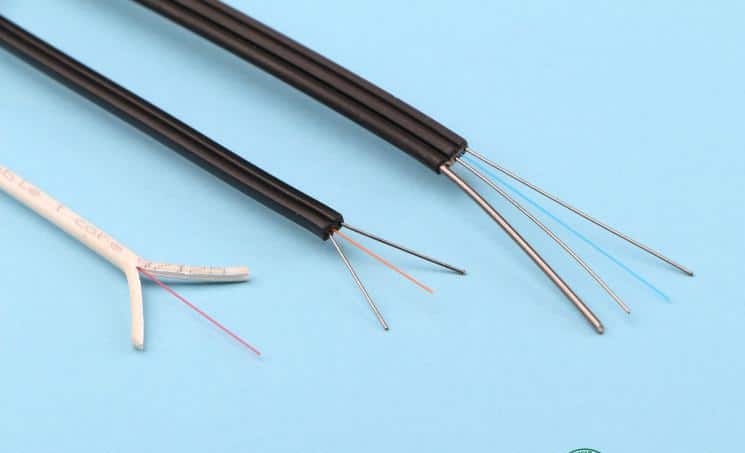
The leather cable is commonly known as an indoor hanging wiring cable. In the case that the domestic fiber access market shows a good momentum of development, fiber access has become a hot spot in the field of optical communications. In the fiber access engineering, the indoor wiring close to the user is the most complicated link. The bending performance and tensile performance of the conventional indoor optical cable cannot meet the requirements of FTTH (Fiber to the Home) indoor wiring.
The access network uses a dish-shaped cable (for indoor wiring) with the optical communication unit (fiber) in the center, two parallel non-metallic reinforcements ( FRP ) or metal reinforcement members placed on both sides , and finally, black or colored poly It is made of vinyl chloride ( PVC ) or low-smoke halogen-free material (LSZH, low-smoke, halogen-free, flame retardant).

Feature

Special bend-resistant fiber to provide greater bandwidth and enhance network transmission performance;

Two parallel FRP or metal reinforcements provide good compression resistance and protect the fiber;

The cable has the advantages of simple structure, lightweight and strong practicability;

Unique groove design, easy to peel, easy to connect, simplify installation and maintenance;

Low-smoke, halogen-free flame-retardant polyethylene sheath or flame-retardant PVC sheath, environmentally friendly.

It can be matched with a variety of field connectors and can be field-proven.

The leather fiber optic cable is characterized by its softness and lightness; it is widely used in the access network; the name of the leather cable: the access network is

introduced into the cable by a butterfly; because of its shape, it is called a butterfly cable. 8-word cable.

product structure

The ordinary leather cable is a standard 8-shaped structure; two parallel reinforcing cores with fiber in the middle; self-supporting leather cable adds a thick steel wire to the structure of ordinary leather cable; overall self-supporting leather The line cable is just one more wire, and the others have not changed.
This type of fiber optic cable has a different structure for each manufacturer. However, it is generally not a metal reinforcing core, and a butterfly-shaped cable is taken as an example. The cross-section is like a butterfly, so it is called. Both sides are reinforcing members in the leather line and optical fibers in the middle.
1. The butterfly-shaped optical cable is divided into indoor and outdoor (inside) and outside, the price difference between the two is large, and the outdoor price is about twice the price of the indoor type. In general, the price factor should be considered when making a specific design. Under normal circumstances, The outdoor fiber optic cable (GYTA-G 652D) is still used outdoors, and the indoor butterfly cable is used for the transition between the two through the fiber box or the joint box.
2. The butterfly cable has a small radius of curvature, lightweight, relatively good bending resistance, easy to fix, and easy termination in the 86 terminal box.
3. Butterfly-shaped fiber-optic cables are available in non-metallic reinforcing members and metal-reinforced members. In view of lightning protection and strong electrical interference, indoor non-metallic reinforcing members butterfly cables should be used.
4, indoor butterfly cable has 1 core, 2 core, 3 core, 4 core, and other specifications, residential users should choose single-core cable for butterfly-shaped household cable; business users can access butterfly cable for 2–4 Core cable design.
The connection has a cold connection and welding.
The cold connection is to install the fiber end face by connecting the fiber end face and connect it with the flange head.

Applications

For indoor wiring, the end user directly uses the cable;
Used for building incoming optical cables;
User wiring for FTTH.

Executive standard

YD/T1997-2009 The access network uses a dish to introduce fiber optic cable.

Structural parameters

Reinforcement type Cable size (mm) Allowable tensile force (N)
long/short term
Allowable crushing force (N/100mm)
long/short term
Non-metallic reinforcement 3.0×2.0 40/80 500/1000
Metal reinforcement 3.0×2.0 100/200 1000/2000
coding product name Description
NFC8101F Single core single mode indoor leather cable OS1, non-metallic reinforcement, flame retardant PVC jacket
NFC8102F Double core single mode indoor leather cable OS1, non-metallic reinforcement, flame retardant PVC jacket
NFC8102FL Double core single mode indoor leather cable OS1, non-metallic reinforcement, low smoke zero halogen LSZH jacket
NFC8102 Double core single mode indoor leather cable OS1, metal reinforcement, flame retardant PVC jacket
NFC8102L Double core single mode indoor leather cable OS1, metal reinforcement, low smoke zero halogen LSZH jacket

Disclaimer: All information indicated as other sources is transferred from other platforms, the purpose is to convey more information, does not represent the views and positions of this site. Please contact us if there is any infringement or objection.

Posted on Leave a comment

Fiber definition and technology

optical fiber

The optical fiber is the transmission channel of optical signals and is the key material for optical fiber communication.
The optical fiber consists of a core, a cladding, a coating layer, and a jacket, and is an asymmetrical cylinder of a multilayer dielectric structure. The main body of the core is
silica, which is doped with trace amounts of other materials to increase the refractive index of the material. The outer core has a cladding layer, and the cladding has a
different refractive index from the core and the core has a higher refractive index to ensure that the optical signal is mainly transmitted in the core. Outside the cladding is a
layer of paint that is used primarily to increase the mechanical strength of the fiber so that the fiber is not damaged by external damage. The outermost layer of the fiber is a
jacket and is also protective.
The two main features of an optical fiber are loss and dispersion. The loss is the attenuation or loss of the optical signal per unit length, expressed in dB/km. This parameter is
related to the transmission distance of the optical signal. The larger the loss, the shorter the transmission distance. Multi-microcomputer elevator control systems generally
have a short transmission distance, so in order to reduce costs, plastic optical fibers are mostly used. The dispersion of the fiber is mainly related to pulse broadening. In the
Mitsubishi elevator control system, optical fiber communication is mainly used for data transmission between group control and single ladder and data transmission between
two parallel single ladders. The fiber optic device used in the Mitsubishi elevator is mainly composed of a light source, an optical receiver, and an optical fiber, wherein the
light source and the optical receiver are packaged in a fixed plug of the optical fiber connector, and the optical fiber is connected to the movable plug.

Optical wavelength division multiplexing

WDM (Wavelength Division Multiplexing) technology refers to the use of multiple lasers to simultaneously transmit multiple wavelengths of light on the same fiber. It can

greatly increase the transmission capacity of the fiber transmission system. Currently, 1.6 Tbit/s WDM systems have been commercialized on a large scale. In order to further

increase the capacity of optical fiber transmission, the DWDM (Dense Wavelength Division Multiplexing) foundation became the main research object in the world after

1995. Lucent Bell Labs believes that the commercial DWDM system capacity can reach 100 Tbit/s. At present, DWDM based on 10 Gbit/s has gradually become the

mainstream of core networks among many operators in China. In addition to the increasing number of wavelengths and transmission capacity of the DWDM system, the

optical transmission distance has also increased from 600 km to over 2000 km. In addition, Coarse Wavelength Division Multiplexing (CWDM) has also emerged in the

expansion of metro optical transport networks, with advantages such as large capacity, short-distance transmission and low cost. The researchers also found that wavelength

division multiplexing of multiple optical time division multiplexed OTDM signals can greatly increase transmission capacity. As long as the appropriate combination can

achieve Tbit / s transmission, it is also the future development direction of optical fiber communication. Most of the transmission experiments in the laboratory over 3 Tbit/s

are implemented in this way.

Optical soliton communication technology

Light is a special ultra-short optical pulse on the order of ps. After long-distance transmission through the fiber, the waveform and speed remain unchanged. Optical soliton

communication uses optical soliton as a carrier to realize long-distance undistorted communication. In the case of zero error, information transmission can reach thousands
of miles. Numerous experiments have shown that it can be used for submarine cable communication, etc., and is suitable for combination with WDM systems to form ultra-
high-speed and large-capacity optical communication. When the single-channel rate reaches 40 Gbit/s or more, the advantages of optical soliton communication are fully

realized.

Fiber access technology

Fiber access using PON technology can be combined with a variety of technologies, such as ATMSDH and Ethernet, to generate APON, GPON, and EPON, respectively. In
contrast, EPON inherits the advantages of Ethernet and the cost is relatively low. After combining with fiber technology, EPON is not limited to local area networks, but also
extends to metropolitan area networks and even wide area networks. Now, fiber-to-the-home adopts EPON technology; GPON has the most advantages in circuit-switched
service support, and can fully utilize existing SDH technology, but the technology is more complicated and the cost is higher; APON will be used to implement FTTH solution.
Disclaimer: All information indicated as other sources is transferred from other platforms, the purpose is to convey more information, does not represent the views and
positions of this site. Please contact us if there is any infringement or objection.

Posted on Leave a comment

Development of optical switching

Development of optical switching
In fact, it can be expressed as communication + exchange.
Optical fiber only solves the transmission problem and needs to solve the problem of optical exchange. In the past, communication networks were made up of metal cables,
which transmitted electronic signals, and exchanges were made using electronic switches. In addition to a short segment of the user’s end, the communication network is an
optical fiber that transmits optical signals. A reasonable approach should be to use optical switching. However, since the optical switching device is not mature, only the
“optical-electric-optical” method can be used to solve the exchange of the optical network, that is, the optical signal is converted into an electrical signal, and after being
exchanged by the electronic, the optical signal is returned. Obviously, it is an unreasonable way, and the effect is not high and uneconomical. Large-capacity optical switches
are being developed to implement optical switching networks, especially the so-called ASON-auto-switched optical networks.

Usually, the information transmitted in the optical network is generally Gbps, and the electronic switch is not competent. It is generally necessary to implement an electronic

exchange in a low-order group. Optical switching enables high-speed XGbDs to be exchanged. Of course, it is not to say that everything must be exchanged by light, especially

the exchange of low-speed, small-particle signals. The mature electronic exchange should be used. It is not necessary to adopt immaturely

Large-capacity optical switching. Currently, in data networks, signals appear in the form of “packets”, using so-called “packet switching.” The particles of the bag are relatively
small and can be exchanged by electrons. However, after a large number of packets in the same direction are aggregated, when the number is large, a large-capacity optical
the switch should be used.
Less channel and large capacity optical switching have been practical. Such as for protection, downlink, and small-scale path scheduling. It is generally realized by the
mechanical optical switch and thermo-optical switch. Due to the limitations of the size, power consumption, and integration of these optical switches, the number of channels
is generally 8-16.
Electronic exchange generally has “space division” and “time division” methods. There are “space division”, “time division” and ” wavelength exchange ” in optical
switching. Optical fiber communication rarely uses optical time division switching.
Optical space switching: Generally, an optical switch can be used to transfer an optical signal from one optical fiber to another optical fiber. The optical switches of air
separation has mechanical, semiconductor and thermo-optic switches. Using integrated technology, the MEM micromotor optical switch was developed with a volume as
small as me. The 1296×1296 MEM optical switch (Lucent) has been developed and is experimental in nature.
Optical wavelength switching: assigns a specific wavelength to each switching object. Thus, a certain specific wavelength can be transmitted to communicate with a specific
object. The key to achieving optical wavelength switching is the development of practical variable wavelength light sources, optical filters, and integrated low power, reliable
optical switch arrays. A cross-connection test system (Corning) combining the space and wavelength of a 640×640 semiconductor optical switch + AWG has been
developed. The use of optical space division and optical wavelength division can constitute a very flexible optical switching network. Japan’s NTT conducted field trials using
wavelength routing exchange in Chitose City, with a radius of 5 kilometers and a total of 43 terminal sections (using 5 nodes) at a rate of 2.5 Gbps.
The automatically switched optical network, called ASON, is the direction of further development.
Disclaimer: All information indicated as other sources is transferred from other platforms, the purpose is to convey more information, does not represent the views and
positions of this site. Please contact us if there is any infringement or objection.

Posted on Leave a comment

Development of optical fiber communication

Development of

Optical fiber communication is the main transmission means of modern communication networks. Its development history is only one or two decades. It has experienced
three generations: short-wavelength multimode fiber, long-wavelength multimode fiber, and long-wavelength single-mode fiber. The use of optical fiber communication is a
major change in the history of communications. More than 20 countries such as the United States, Japan, Britain, and France have announced that they will no longer build
cable communication lines, and are committed to the development of fiber-optic communications. China’s optical fiber communication has entered a practical stage.
The birth and development of optical fiber communications are telecommunications an important revolution in the history of satellite communications, mobile
communications tied to the technology of the 1990s. After entering the 21st century, due to the rapid development of Internet services and the growth of audio, video, data,
and multimedia applications, there is a more pressing need for high-capacity (ultra-high-speed and ultra-long-haul) optical wave transmission systems and networks.
Optical fiber communication is a new communication technology that uses optical waves as a carrier to transmit information and optical fiber as a transmission medium to
achieve information transmission.
The development process of communication is to continuously increase the carrier frequency to expand the communication capacity. The optical frequency as the carrier
the frequency has reached the upper limit of the communication carrier. Because light is an electromagnetic wave with extremely high frequency, the communication capacity
is very large with light as a carrier. It is a thousand times of communication methods in the past, and it has great attraction. Optical communication is the goal that people
have long pursued, and it is also the inevitable direction of communication development.
Compared with the previous electrical communication, the main difference of optical fiber communication is that it has many advantages: it has a wide transmission
bandwidth and large communication capacity; low transmission loss and long relay distance; fine wire diameter and lightweight; the raw material is quartz, saving metal
materials. Conducive to the rational use of resources; strong insulation and anti-electromagnetic interference; also has the advantages of strong anti-corrosion ability, strong
radiation resistance, good routable, no electric spark, small leakage, strong confidentiality, etc., can be used in a special environment or military Used on.
Disclaimer: All information indicated as other sources is transferred from other platforms, the purpose is to convey more information, does not represent the views and
positions of this site. Please contact us if there is any infringement or objection.

Posted on Leave a comment

Detailed introduction of fiber optic transceiver products

One. Overview
* Optical transceiver is an optical signal converter used to convert electrical signals from computer networks into optical signals.
* Our 10/100M adaptive optical transceiver is fully compliant with IEEE802.3 10BaseT, IEEE802.3u 10BaseTX. 10Base-FX standard;
* 10/100M adaptive optical transceiver is divided into multimode fiber transceiver and single mode fiber transceiver;
* Optical transceiver has one RJ45 interface and one SC/ST interface. Used to connect twisted pair and fiber respectively;
* The fiber transceiver has 6 LED indicators: POWER, FX100, TX100, FXlink/Act, TXlink/Act, Fdx.
10/100Base-TX to 100Base-FX SFP Fiber Media Converter
two. Installation and Initialization

Follow these steps to install a 10/100M adaptive fiber transceiver:
1. Connect the fiber jumper or tail cable from the fiber optic terminal box to the fiber transceiver. Please note that the sender (TX) of the other device should be connected to the receiver (RX) of the transceiver, and the receiver (RX) of the other device should be connected to the transmitter (TX) of the transceiver.
2. The UTP jumper connector RJ45 interface from the network device to the fiber optic transceiver, straight or crossing lines selected in accordance with the fiber optic transceiver of claim docking device, generally exchange
required line cross-connect machines, and other network devices address, A straight-through cable is required to connect to single-address network devices such as servers and workstations.
3. Connect the DC plug of the power adapter to the DC socket of the fiber transceiver, and then plug the AC plug of the power adapter into the AC socket. At this time, the POWER indicator of the light transceiver is on, and the other indicators flash in sequence according to the self-test sequence. After the self-test is completed, the working state of the transceiver will be determined according to the state of the network device that is detected by the fiber transceiver, and the indicator light will display the working state of the transceiver at this time.

Three. LED indicator
The fiber optic transceiver has six LED indicators that show the operating status of the transceiver. Based on the LED indicators, it can be determined whether the transceiver is working properly and may have problems, which can help identify the fault. Their functions are as follows:
PWR: Lights up to indicate that the DC5V power supply is working properly.
FX 100: Lights up to indicate that the fiber transmission rate is 100Mbps.
FX Link/Act: The long light indicates that the fiber link is connected correctly, and the light flashes to indicate that there is data in the fiber. Transmission
FDX: Lights up to indicate that the fiber transmits data in full-duplex mode.
TX 100: Lights up to indicate that the twisted pair transmission rate is 100 Mbps; when the light is off, the twisted pair transmission rate is 10 Mbps.
TX Link/Act: The light is long and the twisted pair is connected. The road is connected correctly; the light flashes to indicate that there is data in the twisted pair

.

model
Fiber optic interfaceSC/STSCSCSC
Fiber typeMultimodeMultimodeMultimodeMultimode
Center wavelength850/1310nm1310nm1310nm1310nm
Transmission distance2 km25 km40 km60 km
Minimum transmit power-19.0dBm-15dBm-9.0dBm-4.0dBm
Maximum transmit power-12.0dBm-9.0dBm-5.0dBm0dBm
Receiving sensitivity<-30dBm<-32dBm<-35dBm<-38dBm
Allow link loss11.0dBm17.0dBm26.0dBm34.0dBm

V. Technical parameter
standard: IEEE802.3 10BaseT, IEEE802.3u 10Base-TX, 10Base-FX standard
interface: twisted pair: RJ45
fiber: SC or ST
LED: PWR, FX 100, FX Link/Act, FDX, TX 100 , TX Link/Act
transmission rate: twisted pair: 10Mbps, 100Mbps
fiber: 100mbps
duplex mode: full or half duplex
twisted pair: Category 5 5E
fiber: multimode 50/125, 62.5/125μm
single mode :8.3/125,9/125,10/125μm
Power supply: AC 220V (175-250V), 50Hz
DC: 5V, 1A
Ambient temperature: 0~50 C
Storage temperature: -20~70 C
Humidity: 5%~90%
volume : 26 × 70 × 95mm (height × width × length)VI. Packing list
fiber optic transceiver
AC22V / DC5V power adapter 1 only
instructions for use 1
note: 1. Fiber interface is always set to 100M full duplex mode
2. Double When the twisted-line interface is initialized, its own state is set according to the state of the detected docking device. If the other party’s state is not detected, the state is undefined.
3. Lightning induction damage chip is not covered by the free warranty

Disclaimer: All information indicated as other sources is transferred from other platforms, the purpose is to convey more information, does not represent the views and positions of this site. Please contact us if there is any infringement or objection.

Posted on Leave a comment

Common single mode fiber

Single Mode Fiber: The center core is very thin (the core diameter is generally 9 or 10 μm), and the single-clad outer diameter is 125 μm, which is expressed as 9/125

μm. Only one mode can be transmitted (degenerate two polarization states). Therefore, the inter-mode dispersion is small, suitable for remote communication, but there are

also material dispersion and waveguide dispersion, so that single-mode fiber has high requirements on the spectral width and stability of the light source, that is, the spectral

width is narrow and stable. It’s better.

It was later found that at a wavelength of 1310 nm, the total dispersion of the single mode fiber is zero. From the loss characteristics of the fiber, 1310nm is just a low loss

window of the fiber. Thus, the 1310 nm wavelength region has become an ideal working window for fiber-optic communication and is also the main working band of practical

fiber-optic communication systems. The main parameters of the 1310nm conventional single-mode fiber are determined by the International Telecommunication Union ITU-

T in the G652 recommendation, so this fiber is also called G652 fiber. The vast majority of fiber optic cables that have been laid in China are such fibers. With the successful

advancement of the fiber optic cable industry and semiconductor laser technology, the operating wavelength of the fiber line can be transferred to a lower loss (0.22 dB/km)

1550 nm fiber window.

G.653 single mode fiber

A single-mode fiber that meets ITU-TG653 requirements, often referred to as Dispersion Shifted Fiber, has a zero-dispersion wavelength shifted to a very low loss of 1550

nm. However, the existence of DSF is seriously insufficient. There are harmful nonlinear effects such as four-wave mixing in the low dispersion region around 1550 nm, which

hinders the application of the fiber amplifier in the 1550 nm window.

Four-Wave Mixing (FWM), also known as four-phonon mixing, is an inter-wave coupling effect produced by the real part of the third-order polarization of a fiber medium. It

is due to the interaction of two or three light waves of different wavelengths. This results in the generation of so-called mixing products at other wavelengths or new light

waves in the sidebands. This interaction may occur between signals in a multi-channel system and can produce multiple parametric effects such as triple frequency, sum

frequency, and difference frequency.

The reason why the four-wave mixing occurs is that the light at one of the incident lights changes the refractive index of the optical fiber, and the phase of the optical wave

changes at different frequencies, thereby generating a new wavelength of light.

In a DWDM system, four-wave mixing becomes a major factor in nonlinear crosstalk when the channel spacing and fiber dispersion are sufficiently small and phase matching

is satisfied. When the channel spacing reaches below 10 GHz, the impact of the FWM on the system will be most severe.

Addax security engineers believe that the impact of four-wave mixing on the DWDM system is mainly manifested in (1) generating new wavelengths, causing loss of optical

energy of the original signal, affecting the signal-to-noise ratio of the system; (2) If the new wavelength produced is the same as or overlaps with the original wavelength,

serious crosstalk is generated. The generation of four-wave mixing requires the phase matching of each signal light. When each signal light is transmitted near the zero

dispersion of the optical fiber, the influence of material dispersion on the phase mismatch is small, so it is easy to satisfy the phase matching condition and easily generate

four waves. Mixing effect.

The channel spacing of current DWDM systems is generally 100 GHz, and zero-dispersion causes four-wave mixing to become the main reason. Therefore, when G.653 fiber

transmission DWDM system is used, it is easy to generate a four-wave mixing effect, and G.652 or G. At 655 fiber, it is not easy to produce a four-wave mixing

effect. However, G.652 fiber has a certain dispersion in the 1550nm window storage. When transmitting the 10G signal, the dispersion compensation should be added. The

dispersion of G.655 fiber in the 1550nm window is small, which is suitable for transmission of a 10G DWDM system…

G.655 single mode fiber

Single mode fiber that meets ITU-TG 655 requirements, often referred to as a non-zero dispersion shifted fiber or NZDSF (=NonZero Dispersion Shifted Fiber). It belongs to

the dispersion-shifted fiber, but the dispersion is not zero at 1550 nm (the dispersion value corresponding to the range of 1530-1565 nm according to ITU-TG655 is 0.1-6.0

ps/nm.km), which is used to balance the four-wave mixing. Linear effect.

Disclaimer: All information indicated as other sources is transferred from other platforms, the purpose is to convey more information, does not represent the views and

positions of this site. Please contact us if there is any infringement or objection.

Posted on Leave a comment

Characteristics affecting optical transmission performance

1. Propagation of light in optical fibers

For step-index fibers, due to the obvious boundary between the core and cladding refractive index distributions, the light waves from a total reflection at the interface

between the core and the cladding interface, and form a zigzag transmission path, guiding the fiber core to propagate forward…

For the graded-index fiber, since the refractive index is continuously changed at the interface, the refractive index at the center of the shaft is the largest, the refractive index

decreases along the radius of the core in a parabolic law, and the refractive index at the edge of the core is the smallest, so the light wave is Continuous refraction occurs in the

core, forming a refracting line similar to a sinusoidal wave passing through the axis of the fiber, directing the light wave to propagate forward along the core.

2. Loss and dispersion are the two most important transmission characteristics of optical fibers, which directly affect the performance of the optical transmission.

(1) Optical fiber transmission loss: Loss is one of the important factors affecting the transmission distance of the system. The loss of the optical fiber itself mainly

includes absorption loss and scattering loss.

Absorption loss is due to the fact that part of the light energy is converted into heat energy during transmission.

Scattering loss is caused by the uneven or defective refractive index of the material, distortion or roughness of the surface of the fiber.

Of course, there are some losses in the fiber-optic communication system that are not due to the fiber itself, including connection loss, bending loss, and microbend

loss. TThe magnitude of these losses will directly affect the length of the fiber transmission distance and the choice of relay distance.

(2) Optical fiber transmission dispersion: Dispersion is the time spread of the optical pulse signal transmitted in the optical fiber and reaching the output end.

The cause is the different frequency components of the optical pulse signal, different modes, and the waveform distortion caused by the different time at the end of the

transmission due to the different speeds.

Dispersion results: This distortion causes communication quality to degrade, thereby limiting communication capacity and transmission distance.

Disclaimer: All information indicated as other sources is transferred from other platforms, the purpose is to convey more information, does not represent the views and

positions of this site. Please contact us if there is any infringement or objection.