Posted on Leave a comment

OM3 / OM4-based Fibre Channel connectivity solution

ICCSZ News In the enterprise data center, OM3/OM4 multimode fiber is currently used as the Fibre Channel FC transmission medium to connect servers and storage devices. High-performance server and storage technologies continue to drive FC channel rates, while also requiring FC channels for higher reliability and lower cost. This article will focus on high-speed OM3/OM4 multimode fiber connections between servers and storage devices.

FC Fibre Channel – supports high rates

    Fibre Channel FC is the preferred choice for server and storage connectivity due to its high speed, low jitter, and high reliability. As server and storage technologies continue to evolve, the rate of Fibre Channel FC continues to increase.

Rate map of Fibre Channel released by FCIA

    A detailed description of past, present, and future Fibre Channel

    Today, multi-core processor servers deployed in enterprise data centers range from 4 to 12 core processors. Each processor typically has 2 GHz of processing power. With 12 cores, the processor capacity is 24 GHz. In addition, the server now generally uses PCIe3 (8G / line) and PCIe4 (16G / line) bus interface, has gradually solved the bus interface bottleneck caused by the increase in the number of processors. Increased server computing power requires higher Ethernet data rates and higher Fibre Channel rates. Future server bandwidth trends will be Ethernet 50/100Gbps (NIC) and 64 Gbps Fibre Channel (HBA) interconnects.

    Compared to traditional hard disk drives (HDDs), all-flash arrays (AFAs) offer high data density, high endurance, low energy consumption, and rack space savings, significantly improving storage performance. According to the Brocade demo, it uses 32G Fibre Channel to access 8G of flash memory, which is 71% less than the response time of using 8G Fibre Channel.

Data center multimode fiber connection distance

    Based on Ethernet and Fibre Channel transmission standards, technology development, and commercial viability, Corning established a model for data center multimode and single mode fiber connection channel lengths. The data shows that as Ethernet rates increase from 10G to 40G and 100G, and Fibre Channel rates range from 8G to 16G and 32G, data center users deploy OM3/OM4 multimode fiber, with more than 90% of the distance being within 100 meters. In other words, for the vast majority of data center users, the 100-meter channel distance is sufficient for their needs.

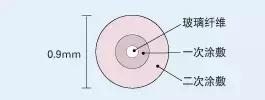
FC Fibre Channel – mainly using OM3/OM4 multimode media

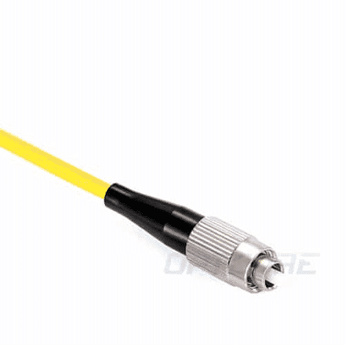
    Fibre Channel FC is a point-to-point connection. OM3/OM4 multimode fiber is the primary medium for short-range transmission with a transmission distance of up to 150 meters. The 16GFC and 32GFC channels are now deployed primarily with OM3/OM4 multimode fiber. In addition, OM3/OM4 multimode fiber uses VCSELs, so it is more economical.

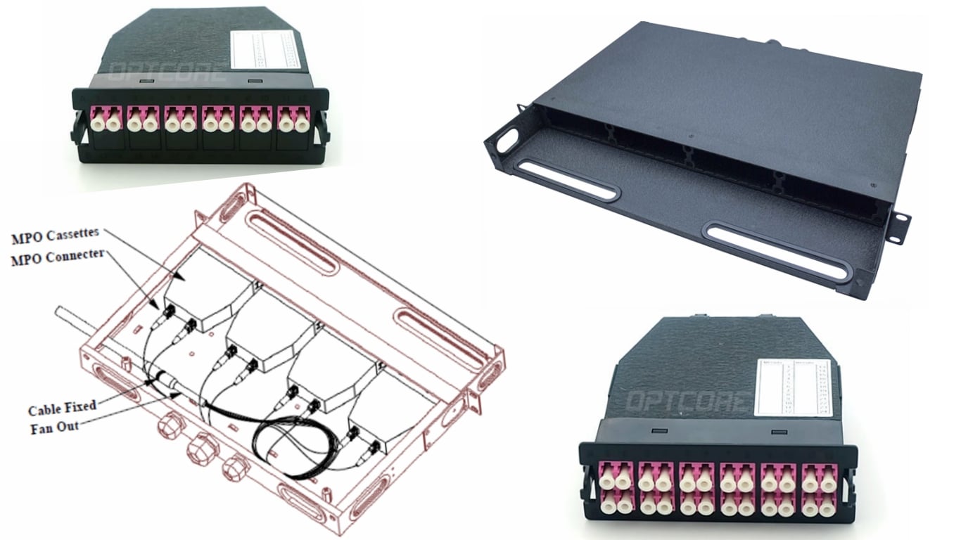
    To date, Fibre Channel FC uses a small form-factor pluggable (SFP+) transceiver with a duplex LC interface in a storage area network (SAN) connection. The pre-terminated MTP cable is usually deployed as a trunk under the bridge or overhead floor between the server cabinet and the storage device cabinet. The MTP/LC module or fan-out jumper is used in the equipment cabinet to convert to the LC connector. Of course, using the MTP/LC fanout jumper can effectively reduce the number of cables and reduce the difficulty of installation and maintenance. At the same time, the MTP/LC fanout jumper provides stepped LC leg length, which can better meet the space of the line card port.

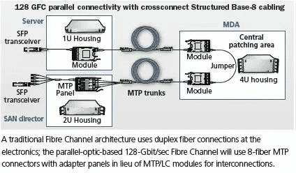
    The Fibre Channel FC-PI6 standard includes the 128GFC protocol, which uses a QSFP transceiver and an 8- or 12-pin MTP interface. The 128GFC uses parallel transmission technology. Parallel transmission differs from the traditional two-core serial method in that it transmits 32GFC per core fiber, namely: 4-core bearer transmits signal (4x32GFC) and 4-core bearer receive signal (4x32GFC). 128GFC is also the first to be defined as a Fibre Channel transmission technology for parallel transmission. Future FC-PI7 will also promote 256 GFC parallel transmission.

    Initially, 128GFC is expected to be deployed on the switch internal link (ISL) and use MTP to connect the entire link. Parallel transmissions will use 8-core MTP connectors and adapter panels instead of MTP-to-LC interconnects compared to traditional Fibre Channel duplex serial connections.

    The fiber-optic transmission channel FC needs higher speed to improve the response speed of the server and storage devices. Currently, the distance of the FC channel is mostly within 100 meters, so the OM3/OM4 multi-mode fiber connection is a wise choice for cost-effective.

Disclaimer: All information indicated as other sources is transferred from other platforms, the purpose is to convey more information, does not represent the views and positions of this site. Please contact us if there is any infringement or objection.

Posted on Leave a comment

Precautions for fusion work

Precautions for fusion work

This is a method of aligning the outer diameter and aligning the core by arranging the optical fiber with a high-precision V-groove and utilizing the effect of the surface tension generated by melting the optical fiber. Recently, due to the development of manufacturing technology, the dimensional accuracy of the position of the optical fiber core and the like is improved, so that low-loss wiring can be realized. This method is mainly used for multi-core one-time wiring.

1 Insert the fiber protection sleeve

A fiber optic protection sleeve is used to protect the fiber exposed at the junction. Since the protective sleeve cannot be inserted, don’t forget to insert it.

2 remove the core coating layer

Because the glass portion of the fiber is to be exposed, the coating layer is removed using stripping pliers.

(Note) Since the coating layer waste remains on the stripping pliers after removing the coating layer, remove the coating layer waste and clean the blade.

(Note) When removing the coating layer of the ribbon core, a heated stripper is used. In order to carry out the removal work steadily, the coating layer is heated for about 5 seconds, and then the coating layer is removed.

3 cleaning fiber

After the coating is removed, the glass portion is cleaned with ethanol.

(Note) If residual coating waste is left, shaft misalignment may occur during fusion and wiring loss may increase, so clean it carefully.

(Note) In the case of multi-core optical fibers, the front ends of the optical fibers may stick together due to alcohol, which may cause cutting defects when cutting the optical fibers. Therefore, use your fingers to bounce the front end of the optical fibers.

4 cut off the fiber

Cut according to the operation steps of cutting the fiber.

(Note) The cut will determine the loss characteristics at the time of fusion. In order to reduce the cutting failure, please pay attention to cleaning the fiber holding part of the fiber cutter and the cutting edge.

(Note) Be careful not to bump or touch the front end of the fiber after cutting. Failure to do so may result in poor wiring.

(Note) Please be careful not to let the fiber waste sprinkle everywhere.

5 fusion

Perform the fusion operation according to the operation steps of the fusion machine.

(Note) If there is garbage in the V-groove and the jig of the fusion splicer, the loss due to the shaft misalignment may occur, so clean it thoroughly.

(Note) If the two-way observation check function before wiring is provided, the abnormality of the cutting state can be detected before wiring.

(Note) When the fiber is bent, gently straighten it with your fingers to bend the fiber downwards.

6 fusion joint reinforcement

A fiber protection sleeve is placed on the fiber fusion portion, and the core wire is reinforced on the heating machine.

(Note) When moving the core wire, be careful not to bend or twist the fiber. Otherwise, the cable will be damaged and broken.

(Note) When setting the fiber protection sleeve, make the center of the fiber protection sleeve and the center of the wiring unit basically the same.

(Note) When reinforcing the core wire, be sure to avoid bending the glass part.

Disclaimer: All information indicated as other sources is transferred from other platforms, the purpose is to convey more information, does not represent the views and positions of this site. Please contact us if there is any infringement or objection.

Posted on Leave a comment

Types and principles of fiber fusion

Types and principles of fiber fusion

Fiber optic wiring technology can be divided into fusion, mechanical splicing, and connector wiring. Fusion and mechanical splicing are permanent wirings, and connector wiring can be repeatedly removed. Optical connector wiring is mainly used for wiring points that must be switched during the operation and maintenance of optical services. Permanent wiring is mainly used in other places.

Fusion is a wiring technique that uses the heat generated by the discharge between the electrodes to melt the fiber. The fusion method is divided into the following two categories.

(1) Optical fiber core alignment method

This is a method in which the core of the optical fiber is observed under a microscope, and the center axis of the core wire is aligned by image processing, and then the discharge is performed. Positioning is performed in two directions using a fusion machine configured with a two-way viewing camera.

(2) Fixed V-groove alignment method

This is a method of aligning the outer diameter and aligning the core by arranging the optical fiber with a high-precision V-groove and utilizing the effect of the surface tension generated by melting the optical fiber. Recently, due to the development of manufacturing technology, the dimensional accuracy of the position of the optical fiber core and the like is improved, so that low-loss wiring can be realized. This method is mainly used for multi-core one-time wiring.

Disclaimer: All information indicated as other sources is transferred from other platforms, the purpose is to convey more information, does not represent the views and positions of this site. Please contact us if there is any infringement or objection.

Posted on Leave a comment

The principle of loss in fiber optic wiring

The principle of loss in fiber optic wiring

The fiber optic wiring must be such that the core portion through which the light passes is positioned correctly.

The wiring loss of the optical fiber is mainly caused by the following reasons.

(1) Axis offset

The optical axis offset between the connected fibers can cause wiring loss. In the case of a generalized single mode fiber, the wiring loss is approximately the square of the axis offset multiplied by a value of 0.2. (For example, when the wavelength of the light source is 1310 nm, the wiring loss is about 0.2 dB when the axis shift is 1 μm)

(2) Angle shift

The angular offset between the optical axes connecting the fibers can cause wiring losses. For example, if the angle of the section cut by the fiber cutter before the fusion becomes large, the fiber is wired in an inclined state, so care must be taken.

(3) gap

The gap between the end faces of the fibers causes wiring loss. For example, if the end faces of the fibers that are mechanically spliced ​​are not properly bonded, they can cause wiring loss.

(4) Reflection

When there is a gap in the end face of the fiber, due to the difference in refractive index between the fiber and the air, the wiring loss is caused by the reflection of a maximum of 0.6 dB. Also, in order to prevent light breakage, it is important to clean the fiber end face on the optical connector. However, there is a loss of rubbing on the end face of the optical connector other than the end face of the optical fiber. Therefore, it is important to clean all the end faces of the optical connector.

Disclaimer: All information indicated as other sources is transferred from other platforms, the purpose is to convey more information, does not represent the views and positions of this site. Please contact us if there is any infringement or objection.

Posted on Leave a comment

Fiber construction

Fiber construction

The optical fiber for communication is composed of glass that transmits optical signals by total internal reflection. The glass fiber has a standard diameter of 125 microns (0.125 mm) and is covered with a resin protective coating of 250 microns or 900 microns in diameter. The central portion of the transmitted light of the glass fiber is called the “core”, and the cladding around it has a lower refractive index than the core, thereby limiting the loss of light.

Quartz glass is very fragile and therefore covered with a protective coating. There are typically three typical fiber coating layers.

Coating fiber at once

An optical fiber coated with a 0.25 mm diameter UV-curable acrylic coating. It is very small diameter increases the density of the fiber that can be accommodated in the cable and is very common.

Secondary coating fiber

Also known as tight buffer fiber or semi-tight buffer fiber. The surface of the fiber is covered with a thermoplastic resin having a diameter of 0.9 mm. It is more rugged and easy to operate compared to 0.25 mm fiber. Widely used in LAN cabling and fiber optic cables with a small number of fibers.

Ribbon fiber

The ribbon fiber improves the efficiency of the connector assembly and facilitates multi-core fusion, which improves work efficiency.

The ribbon fiber consists of 4, 8 or 12 differently colored fibers with a core count of up to 1,000. The fiber surface is covered with UV-curable acrylate material, which can be easily removed using standard fiber stripping pliers for easy multi-core fusion or removal of a single fiber. With a multi-core splicer, the ribbon fiber can be fused at one time and easily identified in a fiber optic cable with a large number of fibers.

Disclaimer: All information indicated as other sources is transferred from other platforms, the purpose is to convey more information, does not represent the views and positions of this site. Please contact us if there is any infringement or objection.

Posted on Leave a comment

G.652 fiber

G.652 fiber is single-mode fiber.


In the late 1970s, attempts were made to replace the LED source with a successful long-life semiconductor laser to achieve longer communication distances and greater communication capacity, but mode noise occurs when the laser is transmitted in a multimode fiber. In order to overcome the mode noise, in 1980, a single-mode fiber with a zero-dispersion point at 1310 nm (non-dispersion-shifted single-mode fiber, referred to as standard single-mode fiber) was successfully developed. ITU-T recommends that this single-mode fiber be defined as G. 652 fiber.


Because the design idea of a single-mode fiber is to pass only one mode, the mode noise that occurs when transmitting in a multimode fiber does not occur. Therefore, in the mid-1980s, the 140Mbit/s fiber-optic communication system consisting of a laser source and a standard single-mode fiber had a relay distance and transmission capacity far exceeding that of the coaxial cable transmission system, thus gradually replacing the copper cable with the fiber-optic communication system. Communication has become the main means of communication adopted by the telecommunications industry.


The G.652 recommendation is the first version of V1.0 (10/1984) created by ITU-T Group 15 (1981-1984 study period). Later, after 1988, 1993, 1997, and 2000, the V5.0 version was formed. In V5.0, the basic types of G.652 fiber were subdivided into G.652A and G.652B… At the ITU-T15 meeting held in Geneva in 2003 [V6.0 (03/2003)], two types of G.652C and G.652D were added, and it was clarified that the L-band was limited to 1625 nm.


In 2005, some parameters were further revised to form the V7.0 (05/2005) version. The main changes are: MFD tolerance is reduced, the maximum dispersion slope, concentricity error, cladding out-of-roundness, microbend loss are reduced, and the coarse-wavelength division multiplexing optical interface G.695 is added.

In the mid-1980s, a dispersion-shifted fiber (DSF, Dispersion-Shifted Fiber) with a zero-dispersion wavelength shifted from 1.3 μm to 1.55 μm was developed in the mid-1980s for the characteristics that attenuation and zero dispersion were not at the same operating wavelength. The ITU has coded this fiber as G.653.


However, the dispersion-shifted fiber has a dispersion of 1.55 μm at zero, which is not conducive to multi-channel WDM transmission. When the number of channels used is large, the channel spacing is small, and four-wave mixing (FWM) occurs at this time to cause crosstalk between channels. If the dispersion of the fiber line is zero, the interference of the FWM will be very serious; if there is trace dispersion, the FWM interference will decrease. In response to this phenomenon, a new type of optical fiber, namely non-zero dispersion fiber (NZ-DSF), G.655, has been developed.


The fiber has a minimum dispersion near 1.3μm, which is called zero-dispersion wavelength. This is the reason why the early fiber optic communication uses 1.3μm as the working wavelength. If the fiber material and the radius of the fiber core are changed, the zero-dispersion wavelength will have corresponding Change. People can use multi-clad fiber to adjust the zero dispersion wavelength in the wavelength range of 1.25–1.65μm.


The fiber that shifts the zero-dispersion wavelength by 1.3μm is called dispersion-shifted fiber.

Disclaimer: All information indicated as other sources is transferred from other platforms, the purpose is to convey more information, does not represent the views and positions of this site. Please contact us if there is any infringement or objection.

Posted on Leave a comment

Fiber knowledge commonly used in weak current engineering

Fiber type

Optical cables are classified into indoor optical cables, outdoor optical cables, branch optical cables, and distribution optical cables depending on the application. Optical fibers can be divided into single mode and multimode according to the transmission mode, so monitoring generally uses single-mode fiber.

Single-mode fiber: An optical fiber that transmits only one mode optical signal. Conventionally, G.652, G.653, G.654, and G.655 are classified into transmission classes. Single-mode optical fiber transmits hundreds of megabits of signals up to several tens of kilometers.

Multimode fiber: A fiber that can transmit multiple modes of optical signals. It is G.651 grade. It is divided into OM1, OM2, and OM3 according to the optical mode. The maximum transmission distance of multi-mode fiber transmission is 100 kilometers.

Fiber laying method

Conventional outdoor optical cables are containers with loose tubes as the core, which is the most common fiber core laying method.

Indoor fiber optic cables are often laid tightly.

The core of the large-core optical cable also has a fiber core laminated in a strip form.

Cable structure

1 The most common cable structure is a layer-wound cable. The cable with more than 12 cores is generally of this kind. The cable cavity can accommodate multiple loose tubes, and the loose tube is the basic unit. Each loose tube can accommodate 6- 12-core core; the layer-wound cable is the center reinforcement member, and the loose tube is wrapped around the center reinforcement core. For practical applications, the core needs to be covered with different colors, a total of 12 colors, and the loose-layer cable is loose. The number of tubes is generally also less than 12, so the number of cores of the stranded cable is generally from 12 cores to 144 cores.

2 The structure of the outdoor optical cable below 12 cores is generally the center beam tube type. This type of optical cable has a central loose tube built in, which can contain 1-12 cores, and the outer sheath contains two parallel wires.

3 ribbon cable, also known as skeleton slot structure, is generally used as a cable structure with a large number of cores.

Fiber optic equipment

Optical fiber distribution frame (box): The fiber terminal box is used to protect the fiber and the pigtail. The pigtail is used to connect the fiber transceiver, fiber switch or optical transceiver.

Fiber optic terminal box (connector or splice tray): The fiber optic splice box fuses two fibers together.

Pigtail: One end of the fiber pigtail is fused to the fiber and the other end is connected to a fiber transceiver or fiber switch.

ODF fiber distribution frame and optocoupler: In some large and medium-sized monitoring projects, equipment such as ODF fiber distribution frame and optical coupler may be used. ODF optical distribution frame is mainly used in the equipment room, which can make many optical fibers more regular. Easy to maintain.

Optical fiber transceiver: Also known as the photoelectric converter, the device that converts the optical port and the electrical port is used in pairs. The electrical port is connected to the switch, and the optical port is connected to the fiber pigtail.

Fiber optic module: The main application of the fiber optic module and the fiber switch can directly connect the fiber pigtail to the switch through the fiber module, eliminating the fiber transceiver, but the price of the fiber switch is relatively high.

Disclaimer: All information indicated as other sources is transferred from other platforms, the purpose is to convey more information, does not represent the views and positions of this site. Please contact us if there is any infringement or objection.


Posted on Leave a comment

What are the classifications of fiber distribution frames?

The optical fiber distribution frame is connected to the optical fiber connector. In the integrated wiring, the optical fiber distribution frame appears after the optical fiber appears, and the optical fiber generally appears in the vertical subsystem, then the problem comes, what is the optical distribution frame? classification? What are the functions of the fiber distribution frame? How to calculate the fiber distribution frame?


1. What are the classifications of optical distribution frames?

Unit type

A unitized fiber distribution frame is a unit in which multiple units are mounted, each unit is a separate fiber distribution frame. The patch panel not only retains the characteristics of the original small and medium-sized optical fiber distribution frame, but also provides space utilization through the structural deformation of the frame, and is a common structure in the early stage of the large-capacity optical fiber distribution frame. However, due to its inherent limitations in space provision, there is some inconvenience in operation and use.

Drawer type

The drawer type fiber distribution frame also divides a frame into a plurality of units, each unit consisting of one or two drawers. When welding and adjusting the thread, the corresponding drawer is pulled out to operate outside the rack, so that there is a large operation space, so that the units do not affect each other.

The drawer is provided with locking devices in both the pull-out and push-in states to ensure stable and accurate operation and safe and reliable connection of the components in the unit.

Although such a fiber distribution frame ingeniously provides a large space for the operation of the optical cable terminal, as with the unit type, the maximum convenience is not provided in the storage and deployment of the optical connection line. This type of rack is currently the most common form.

Modular

The modular structure divides the fiber distribution frame into a plurality of functional modules, the fusion, wiring, connection line storage and other functional operations of the optical cable are respectively completed in each module, and the modules can be assembled and installed in a common rack as needed. Inside. This structure provides maximum flexibility and better meets the needs of communication networks.

The modular high-capacity optical fiber distribution frame adopts a unique structure such as a panel and a drawer to make the welding and adjusting operation of the optical fiber more convenient. In addition, the vertical wire through and the intermediate distribution frame are used to effectively solve the cloth of the pigtail. Put and store problems. Therefore, it is the most popular type of large-capacity fiber distribution frame, but its cost is relatively high.

Second, what are the functions of the fiber distribution frame?

Optical fiber distribution frame plays an important role in the safe operation and flexible use of optical fiber communication networks, which are embodied in the following four aspects:

After the fiber jumper enters the rack, the fiber distribution frame can fix the fiber jumper to the frame, and mechanically fix the outer sheath and the reinforcing core to protect the fiber jumper from external mechanical damage.

The fiber distribution frame adopts a box structure, which saves space and optimizes cable management.

The high-density pre-terminated system used in fiber distribution frames enhances network performance and makes the network reliable and scalable.

Fiber distribution frames enable easy and fast deployment of high-density interconnects and cross-connects in the data center, simplifying cabling deployments, increasing wiring density, and effectively reducing cabling failures and making cabling flexible.

Third, how to calculate the fiber distribution frame

Take 6-core indoor multimode fiber and 24-port fiber distribution frame as an example:

Assuming there are a central computer room and 5-floor wiring closets, then it is certain that there are 5 fibers.

At this time, the fiber distribution frame is 5 (one per floor wiring) +1 (one in the central room) = 6

Center room fiber distribution frame = 4 (4 core fiber) * 5 (5 fibers) = 20, 20 < 24, so only one is enough, if it is 10 fibers, it is 4 * 10 = 40, 40<48, at this time the center room needs 2 lights.

There is also a situation that is often encountered in actual operation. On the first floor, there is a central computer room and a floor wiring closet. In this case, if everything is in the same cabinet, the fiber can be combined into the same optical distribution. . for example.

6-core indoor multimode fiber and 24-port fiber distribution frame, one central computer room and 5-floor wiring closets

If the central computer room and the floor wiring closet on the 1st floor are on the 1st floor, there are 24 fiber points on the 1st floor (4*5+4), just one 24-port light is enough, so this time We can also solve the problem with 5 light distributions.

Regarding the knowledge about optical fiber distribution frames, today’s Xiaobian will explain to you here first. It is also an extremely important and complicated task in the selection of optical fiber distribution frames. We should fully consider various situations according to specific situations. Factors, based on repeated comparisons, can select a fiber distribution frame that best meets current needs and future development.

(This article is from the Internet, compiled and edited by thousands of hackers. If there is any infringement, please contact to delete.)

This article was first published in the thousand integrated wiring network: http://cabling.qianjia.com/html/2019-04/24_334470.html

Disclaimer: All information indicated as other sources is transferred from other platforms, the purpose is to convey more information, does not represent the position and position of the site and is responsible for its authenticity. If there is any infringement or objection, please contact us to delete.

Posted on Leave a comment

Fiber optic knowledge

Fiber optic knowledge

1 The tensile strength of the fiber is very high, close to the tensile strength of the metal;

2 The ductility of the fiber (1%) is worse than that of the metal (20%);

3 When there are cracks in the fiber, bubbles or debris, under certain tension, it is easy to break;

4 fiber rainwater is easy to break, and the cutting loss is greatly increased;

5 Loss increases with decreasing temperature at low temperatures;

6 Fibers need to be protected from mechanical properties and require waterproof protection to ensure transmission performance.

Wavelength: Communication window of optical fiber communication optical signal, wherein 850, 1310nm is a multi-mode fiber communication window, which is a short-wavelength window; 1310, 1550, 1640nm, etc. is single-mode optical fiber communication with a long-wavelength window.

Simplex: The signal on the communication is only received or not sent, and the one-way communication is understood to be that only one optical fiber is received or only the optical signal is transmitted.

Duplex: Both receiving signals and transmitting signals, which are divided into half-duplex and full-duplex. Half-duplex can be understood as a core optical core. After receiving the signal, the signal can be sent through the same core fiber, but only at this time. Can not send signals cannot be received; and full-duplex is still using a core fiber while receiving signals can continuously send signals, receiving and transmitting two kinds of communication without interference, generally through frequency division multiplexing, time division multiplexing and waves Divided by multiplexing.

Disclaimer: All information indicated as other sources is transferred from other platforms, the purpose is to convey more information, does not represent the views and positions of this site. Please contact us if there is any infringement or objection.

Posted on Leave a comment

Introduction of optical fiber

1 Overview

Fiber and coaxial cables are similar except that there is no mesh shield. The center is the light-transmitting glass core. In a multimode fiber, the core has a diameter of 15 mm to 50 mm, which is roughly equivalent to the thickness of a human hair. The single-mode fiber core has a diameter of 8 mm to 10 mm. The outside of the core is surrounded by a glass envelope having a lower index of refraction than the core to maintain the fiber within the core. Next to it is a thin plastic jacket to protect the envelope. The fiber is usually bundled and protected by an outer casing. The core is usually a double-layer concentric cylinder made of quartz glass with a small cross-sectional area, which is brittle and easily broken so that a protective layer is required. Its structure is shown in Figure 1.

The fiber on the land is usually buried 1 meter underground, sometimes damaged by underground small animals. Near the coast, the transoceanic fiber casing is buried in the ditch. In deep water, they are at the bottom and are most likely to be bitten by fish or crashed by fishing boats.

2, classification

Optical fiber is mainly divided into the following two categories:

1) Transmission point modulus class

Transmission point analog-to-digital single mode Fiber (Single Mode Fiber) and multimode fiber (Multi-Mode Fiber). The single-mode fiber has a small core diameter and can only be transmitted in a single mode at a given operating wavelength, with transmission bandwidth and large transmission capacity. Multimode fiber is an optical fiber that can transmit simultaneously in multiple modes at a given operating wavelength. Multimode fiber has poorer transmission performance than single mode fiber.

2) Refractive index distribution class

Refractive index distribution fibers can be classified into hopping fibers and grading fibers. The refractive index of the hopping fiber core and the refractive index of the protective layer are both constant. At the interface between the core and the protective layer, the refractive index changes stepwise. The refractive index of the graded fiber core decreases with a certain radius as the radius increases and decreases to the refractive index of the protective layer at the interface between the core and the protective layer. The change in the refractive index of the core approximates the parabola. The refractive index distribution type fiber beam transmission is shown in Fig. 2.

3, the connection method

There are three ways to connect the fiber. First, they can be plugged into the connector and plugged into a fiber optic socket. The connector loses 10% to 20% of the light, but it makes it easy to reconfigure the system.

Second, it can be joined mechanically. The method is to place one end of two carefully cut fibers in a sleeve and then clamp them. The fiber can be adjusted through the junction to maximize the signal. The mechanical combination requires trained personnel to take about 5 minutes to complete, and the loss of light is about 10%.

Third, the two fibers can be fused together to form a solid connection. The fiber formed by the fusion method is almost the same as the single fiber, but it also has a little attenuation. For all three connection methods, there is a reflection at the junction and the reflected energy interacts with the signal.

4, send and receive

There are two types of light sources that can be used as signal sources: light-emitting diodes (LEDs) and semiconductor lasers (LDs). They have different characteristics, as shown in the following table.

projectledSemiconductor laser
Data ratelowhigh
modeMultimodeMultimode or single mode
distanceshortlong
Life cyclelongshort
Temperature sensitivitySmallerMore sensitive
CostLow costexpensive

The receiving end of the fiber is made up of a photodiode that gives a point pulse when it encounters light. The response time of a photodiode is typically 1 ns, which is why the data transfer rate is limited to 1 Gb/s. Thermal noise is also a problem, so the light pulse must have enough energy to be detected. If the pulse energy is strong enough, the error rate can be reduced to a very low level.

5, the interface

There are two types of interfaces currently in use. The passive interface is formed by two streets fused to the main fiber. One end of the connector has a light emitting diode or laser diode (for transmission). At the other end, there is a photodiode (for receiving). The joint itself is completely passive and therefore very reliable.

Another type of interface is called an active repeater. The input light is converted into an electrical signal in the repeater, and if the signal has been attenuated, it is re-amplified to the maximum intensity, then converted to light and sent out. Connected to the computer is a common copper wire that enters the signal regenerator. There is now a pure optical repeater that does not require optoelectronic conversion and can, therefore, operate at very high bandwidth.

Disclaimer: All information indicated as other sources is transferred from other platforms, the purpose is to convey more information, does not represent the views and positions of this site. Please contact us if there is any infringement or objection.