
Foreword:
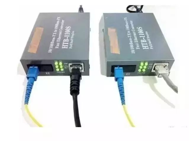
Our commonly used fiber optic transceivers have 6 indicators, so what does each indicator mean? Do all the indicators light up to indicate that the fiber transceiver is working properly?
PWR: Lights up to indicate that the DC5V power supply is working properly.
FDX: Lights up to indicate that the fiber transmits data in full duplex mode;
FX 100: Lights up to indicate that the optical fiber transmission rate is 100Mbps;
TX 100: The light is on, indicating that the twisted pair transmission rate is 100 Mbps, and the light is off, indicating that the twisted pair transmission rate is 10 Mbps;
FX Link/Act: The long light indicates that the fiber link is connected correctly; the flashing light indicates that data is being transmitted in the fiber;
TX Link/Act: The long light indicates that the twisted pair link is connected. When the light is on, the data in the twisted pair is transmitted at 10/100M.
If the optical transceiver is working properly, the PWR power indicator must be steady on. The FX-LINK/ACT fiber link indicator and the TX-LINK/ACT network link indicator must be on or blinking. If the LINK/ACT indicator is off. Check whether the link is normal. The FDX working mode indicator, FX-100 fiber rate indicator and TX-100 network rate indicator are not on the fiber transceiver.
1. The function of the indicator light of the optical transceiver and the method for determining the fault
1. First, do you see if the indicator of the fiber transceiver or optical module and the twisted pair port indicator are on?
- A. If the optical port (FX-LINK/ACT) indicator of the transceiver is not lit, please confirm whether the fiber link is correct cross-link, fiber-optic jack TX-RX; RX-TX.
- B. If the optical port (FXFX-LINK/ACT) indicator of the A transceiver is on and the optical port (FXFX-LINK/ACT) indicator of the B transceiver is not lit, the fault is on the A transceiver side: one possibility is: The A transceiver (TX) optical transmission port is broken because the optical port (RX) of the B transceiver does not receive the optical signal; the other possibility is that the optical link of the A transceiver (TX) optical transmission port has Problem (the cable or fiber jumper may be broken).
- C. The twisted pair (TXFX-LINK/ACT) indicator does not light. Please make sure that the twisted pair cable is faulty or connected incorrectly? Please use the continuity tester (although some transceivers’ twisted pair indicators must be on after the fiber link is connected).
- D. Some transceivers have two RJ45 ports: (To HUB) indicates that the connection line connecting the switches is a straight-through line; (To Node) indicates that the connection line connecting the switches is a cross-line.
- E. Some transceivers have an MPR switch on the side: the connection line connecting the switch is a straight-through mode; the DTE switch: the connection line connecting the switches is a cross-line mode.
2. Is the optical cable and fiber jumper broken?
- A. The cable on/off detection: use laser flashlight, sunlight, illuminator to illuminate one end of the cable connector or coupler; see if there is visible light on the other end? If there is visible light, the cable is not broken.
- B. Optical fiber connection continuity detection: use laser flashlight, sunlight, etc. to illuminate the fiber jumper; see if there is visible light on the other end? If there is visible light, the fiber jumper is not broken.
3. Is there a mistake in the half/full duplex mode?
Some transceivers have FDX switches on the side: full duplex; HDX switches: half duplex.
4, using optical power meter instrument detection
The luminous power of a fiber optic transceiver or optical module under normal conditions:
Multimode 2Km: between -10db and 18db;
Single mode 20 km: between -8 dB and 15 dB;
Single mode 60 km: between -5db and 12db;
If the luminous power of the optical transceiver is between -30db and 45db, then it can be judged that there is a problem with this transceiver.
Second, common faults and solutions
According to the daily maintenance and the problems that the users have summed up, I hope to bring some help to the maintenance staff, to determine the cause according to the fault phenomenon, to find the fault point, “the right medicine.”
1. What kind of connection is used when the transceiver RJ45 port is connected to other devices?
Cause: The RJ45 port of the transceiver is connected to the PC network card (DTE data terminal equipment) using a crossover twisted pair, and the HUB or SWITCH (DCE data communication equipment) uses parallel lines.
2. What is the reason why the TxLink light is not lit?
answer:
- 1, wrong twisted pair
- 2, the twisted pair crystal head is in poor contact with the equipment, or the quality of the twisted pair itself
- 3, the device is not connected
3. What is the reason why the TxLink lamp does not flash but is always on after the fiber is normally connected?
the reason:
- 1. The fault is generally caused by the transmission distance being too long;
- 2, compatibility issues with the network card (connected to the PC)
4. What is the reason why the Fxlink light does not illuminate?
the reason:
- 1. The fiber optic cable is connected incorrectly, and the correct connection method is TX-RX, RX-TX or fiber mode is wrong;
- 2. The transmission distance is too long or the intermediate loss is too large, exceeding the nominal loss of the product. The solution is to take measures to reduce the intermediate loss or replace it with a transmission distance longer.
- 3. The operating temperature of the fiber optic transceiver is too high.
5. What is the reason why the Fxlink light does not flash but is always bright after the fiber is connected normally?
Cause: The fault is generally caused by the transmission distance being too long or the intermediate loss is too large, exceeding the nominal loss of the product. The solution is to minimize the intermediate loss or replace it with a transceiver with a longer transmission distance.
6. What should I do if the five lights are all on or the indicator is normal but not transferable?
Reason: Generally, the power is turned off and restarted.
7. What is the ambient temperature of the transceiver?
Cause: The fiber optic module is greatly affected by the ambient temperature. Although it has its own built-in automatic gain circuit after the temperature exceeds a certain range, the optical power of the optical module is affected and decreased, which weakens the quality of the optical network signal and causes packet loss. The rate rises and even disconnects the optical link; (typical fiber optic modules can reach 70°C)
8. What is the compatibility with the external device protocol?
the reason:
Like the 10/100M switch, the 10/100M optical transceiver has a certain limit on the frame length, generally not exceeding 1522B or 1536B. When the switch connected at the central office supports some special protocols (such as Ciss ISL), The packet overhead is increased (the packet cost of the ISL of the Ciss is 30 Bytes), which is exceeded by the upper limit of the frame length of the optical transceiver. This indicates that the packet loss rate is high or not. In this case, the MTU of the terminal device needs to be adjusted. The overhead of the general IP packet is 18 bytes, and the MTU is 1500 bytes. Currently, the high-end communication equipment manufacturer has an internal network protocol, which generally adopts a separate packet method, which will increase the overhead of the IP packet. If the data is 1500 bytes, IP. After the packet, the size of the IP packet will exceed 18 and be discarded), so that the size of the packet transmitted on the line is satisfactory to the network device’s limitation on the frame length.
9. After the chassis has been working normally for a while, why is it that some cards are not working properly?
the reason:
Early chassis power supplies used relays. Insufficient power supply margin and large line loss are major problems. After the chassis works normally for a period of time, some cards may not work properly. When some cards are pulled out, the remaining cards work normally. After the long-term operation of the chassis, the connector oxidation causes a large joint loss. This power supply falls beyond the regulations. The required range may cause the chassis card to be abnormal. The power supply switching of the chassis is protected by a high-power Schottky diode to improve the form of the connector and reduce the power drop caused by the control circuit and the connector. At the same time, the power redundancy of the power supply is increased, which makes the backup power supply convenient and safe, and makes it more suitable for the long-term uninterrupted work.
10. What function does the link alarm provide on the transceiver?
Cause: The transceiver has a linked alarm function (linkless). When a certain fiber is dropped, it will be automatically fed back to the electrical port (that is, the indicator on the electrical port will also be extinguished). If the switch has network management, it will be reflected in the switch immediately. Network management software. Third, the fiber transceiver should pay attention to matters
1. Does the optical transceiver itself support full-duplex and half-duplex?
Some chips on the market can only use full-duplex environment at present, and can’t support half-duplex. If you receive another brand of the switch (SWITCH) or hub (HUB), and it uses half-duplex mode, it must be It can cause serious conflicts and packet loss.
2. Have you tested the connection with other fiber optic transceivers?
At present, there are more and more optical transceivers on the market. For example, if the compatibility of transceivers of different brands has not been tested beforehand, it will also result in packet loss, long transmission, and rapid and slow.
3. Is there a safety device to prevent packet loss?
In order to reduce the cost, some manufacturers use the register data transmission mode when manufacturing the optical transceiver. The biggest disadvantage of this method is that the transmission is unstable and packet loss and the best is to use the buffer circuit design, which is safe. Avoid data loss.
4, temperature adaptability?
When the fiber optic transceiver itself is used, it will generate high heat. When the temperature is too high (not more than 50 °C), whether the fiber optic transceiver works normally is a factor worth considering when purchasing!
Original Article Sourcehttp://www.qianjia.com/html/2019-05/06_335742.html