Posted on Leave a comment

Fiber access equipment and usage diagram

As the demand for different kinds of information is also increasing, the accompanying ever-increasing demand for new services such as IP data, voice, and multimedia images has prompted the network environment of major network operators to become overwhelming. In the past, traditional metropolitan area networks and access networks, which mainly used to carry analog voices, have been unable to meet the requirements of a variety of new service transmission and processing in terms of capacity and interface types. As a result of the rapid advancement of social information, the technologies and equipment that provide new services for metropolitan area networks and access networks have rapidly developed. Among them, the development of MSTP (Multi-Service Transport Platform) and PON (Passive Optical Network) is the most representative. They are based on fiber-optic transmission technology and provide the best of various new service bearers on the metropolitan area network or access network. solution.

Fiber-optic cable access technology is the development direction of broadband networks in the future. Its development is also inseparable from the development and support of fiber access equipment, just like fish and water. Talking about the fiber access equipment has to mention its three generations of development experience: the first generation of large-scale PDH (fiber optic transceiver) equipment, including point-to-point and star-type office equipment, does not have aggregation function. All adopt PDH transmission protocol, and there is no optical interface specification. User services, such as E1 and data services, are multiplexed through the private PDH protocol and transmitted to the central office equipment via optical fibers. The central office equipment taps the PDH optical signal according to the proprietary protocol, and converts it into a PDH interface such as E1, and then connects to the metro backbone/aggregation device through the cable through the DDF distribution frame. Due to the limitations of the PDH protocol, various types of fiber access devices are quickly out of date.

The second generation In view of the defects of the first generation equipment, some PDH equipment manufacturers have developed a piece of second generation equipment, that is, adding an SDH (dense optical wave multiplexing) terminal card to the central office equipment. The private PDH protocol is still used between the central office and the remote device, and the aggregation function is provided at the central office to multiplex the original E1 signal through the SDH terminal card and provide a standard SDH interface. It mainly solves the interconnection problem and unified interface standard between the central office equipment and the metro backbone equipment.

The third generation is SDH pass-through equipment, including converged and non-converged types. Due to the wide coverage of the new services, the new generation of SDH pass-through devices can be automatically adapted to the SDH for transmission according to the SDH specification. The non-aggregated remote device can be directly connected to the metropolitan area network aggregation layer node through the SDH optical interface. There are fewer service interfaces on the aggregation layer network. The aggregation type is inserted into the SDH aggregation device at the central office to aggregate VC12 services from multiple directions to the uplink SDH interface, thus saving the number of STM-1 interface cards on the large-capacity backbone node device. It mainly solves the compatibility problem of each device and is convenient for future upgrade and maintenance.

With the development of fiber access equipment to date, due to the continuous updating of fiber access technologies and the increasing number of manufacturers joining, the categories of fiber access equipment are becoming more and more obvious, mainly in three categories:

(1) Optical fiber communication Continued text components (for communication and computer network terminal connections), such as fiber jumpers, fiber connectors (boxes).

(2) Optical fiber transceiver (for computer network data transmission), such as fiber optic box, fiber coupler and wiring box (rack).

(3) Optical cable engineering equipment, optical cable test instrument (for large-scale engineering), such as optical fiber fusion splicer, optical fiber loss test equipment.

For the first two categories, we can often understand and contact the fiber access equipment products. The following small series introduces two major types of equipment:

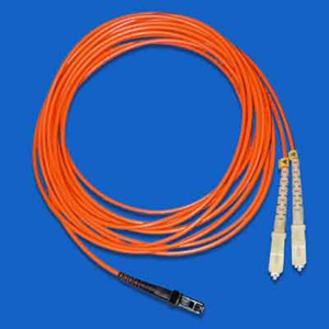
fiber optic communication and text fiber transceivers: the fiber jumper is without connection. The cable pair or cable unit of the unit is used to interface with various links on the distribution frame. Fiber optic patch cords are used for long-haul and local optical transmission networks, data transmission and private networks, and various test and automation systems.
  Fiber optic connector (box)

fiber optic connector (box) is mainly used for the connection between fiber and fiber, fiber and device.
  Fiber optic boxes

Fiber optic boxes are used to transmit digital and similar voice, video and data signals using fiber optic technology. Fiber optic boxes are available for direct or desktop installation. Particularly suitable for high-speed fiber transmission.

  The product shown above is a 100Base-TX twisted pair 100Base-FX multi/single mode fiber optic repeater designed primarily for Fast Ethernet workgroup users who require a long distance, high speed, and wide bandwidth.

  The product shown above is a 10/100M adaptive Fast Ethernet fiber optic transceiver. It can realize the conversion of two different transmission media of twisted pair and optical fiber and relays two different network segments of 10/100Base-Tx and 100Base-FX, which can meet the requirements of long-distance, high-speed and high-bandwidth Fast Ethernet working group users. need.

Fiber module card

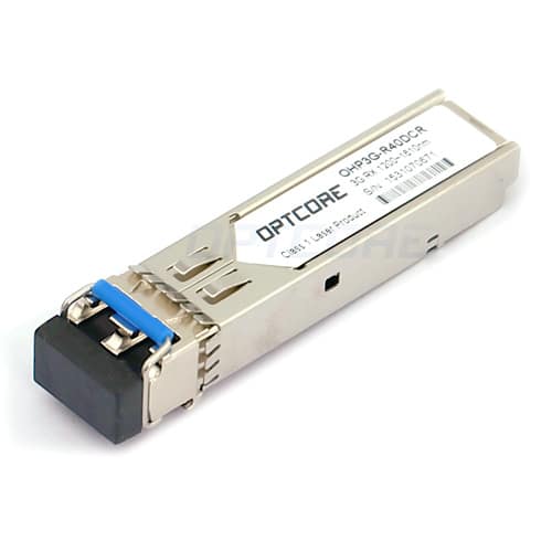
  The Gigabit series fiber-optic module card is used with the switch and uses fiber or Category 5 twisted-pair cable to expand the LAN range and expand the bandwidth. It is suitable for large and medium-sized LANs to expand bandwidth and expand their network coverage. The fiber optic module is fully compliant with the IEEE802.3z protocol and operates in the 850nm and 1300nm modes. It is also fully compliant with the IEEE802.3ab protocol. It is compatible with other devices with the same Gigabit protocol. Due to its small size, it is directly installed inside the switch and requires no additional space. Powered by the switch, it is easy to install and use, and can be used with a variety of switches.

Fiber

Coupler Fiber Coupler (Splitter) is a component that splits optical signals from one fiber into multiple fibers. It belongs to the field of optical passive components, in telecommunication networks, cable TV networks, and users. It is applied in the loop system and the regional network, and the largest item is used in the passive component of the fiber connector. The fiber coupler can be divided into a standard coupler (double branch, unit 1 × 2, that is, the optical signal is divided into two powers), a star/tree coupler, and a wavelength multiplexer (WDM, if the wavelength is high density, that is, the wavelength spacing is narrow, it belongs to DWDM), and the production method includes three types of sintering (Fuse), micro-optics (Micro-Optics), an optical waveguide (Wave Guide), while the production by sintering method is the majority (about 90). %).

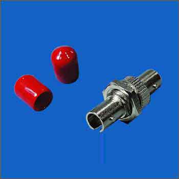
ST coupler
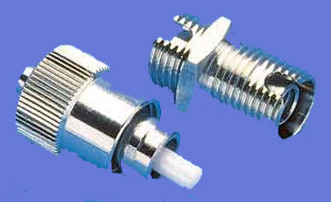
  FC coupler

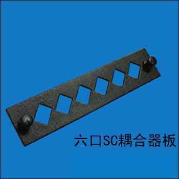
Six-port SC coupler board

  The above products are suitable for transfer between test equipment, local area network, fiber optic CATV and different types of signs.

Single and multimode fiber converter

single and multimode fiber transceivers are used for data communication between optical cables, allowing users to expand the scale of UTP networks using single mode or multimode fiber, and are widely used in Ethernet data communication to extend the transmission distance. The expansion and extension of the network are achieved through fiber optic links.

  Optical transceiver

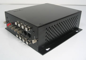
video multiplexer adopts the most advanced digital video, high-speed transmission technology of Gigabit fiber and all-digital uncompressed technology, so it can support any high-resolution motion and still image without distortion transmission; overcome the conventional analog frequency modulation and phase modulation. The amplitude modulation of the multi-channel signal of the amplitude modulation optical transceiver is severe, the interference is serious, the transmission quality is inferior, and the long-term working stability is poor. It can also provide multiple channels of video, audio, data, telephone voice, and Ethernet transmission on the optical fiber at the same time, which greatly saves the investment cost of the user equipment and improves the utilization of the optical cable. Widely used in security monitoring, highways, electronic police, automation, intelligent community, customs, electricity, water conservancy, petroleum, chemical, and many other fields.
  The fiber distribution frame

fiber distribution equipment is designed for the fiber-optic communication equipment room. It consists of a fiber distribution unit and a cabinet or rack. The maximum wiring capacity of each unit is 24 fiber. The unit structure is 19-inch chassis, and the height is generally 9cm. In a standard cabinet or rack. Users can choose the number of units or unit specifications according to actual needs. It can be used as fiber distribution, and can also be used as a cable terminal box; it can be separately assembled into a fiber distribution frame, or it can be integrated with a digital distribution unit and an audio distribution unit in a cabinet/frame to form integrated wiring. frame. The device is flexible in configuration, easy to install and use, easy to maintain, and easy to manage. It is one of the indispensable devices for small and medium-sized fiber-optic communication equipment rooms to realize fiber-optic, fiber-optic, frit, and fiber-optic cable access. Applicable to the fiber termination point in the fiber access network, with the wiring and welding function of the optical cable, which can realize flexible jumper and storage of the optical fiber core.
The above equipment for the fiber access network greatly improves the data transmission and processing capability of the fiber access network, and can bring two advantages:

First, the problem of remote transmission of the access line is solved, and the fiber access network is provided. The coverage is broader. In this way, the number of transit nodes of the entire overlay network can be reduced, and the structure of the network is made simpler.

Second, it can meet the needs of users for a variety of new broadband services and can improve the quality of new business data. This solves the “bottleneck” problem of the traditional copper access network from the core technology and lays the foundation for the realization of the “fiber to the home” dream.

Therefore, the future fiber access network should become the main force of the Internet information highway.

Original Article Source https://www.mscbsc.com/viewnews-39311.html

Posted on Leave a comment

Talking about the testing and troubleshooting equipment of optical fiber network

In recent years, as people’s requirements for broadband speed are getting higher and higher because the performance of optical fiber is superior to that of copper cable, it is widely used in the backbone construction of broadband projects. At the same time, due to the increasing coverage of optical fibers, the detection of optical fiber faults is becoming more and more important. What methods can be used to eliminate the failure of optical components?

First of all, to eliminate the failure of optical components, it is necessary to pass the test, then what are the test and measurement equipment of the optical network? At present, the super six network cable manufacturers Weikang understand that there are mainly three kinds of instruments. They are optical loss test equipment (also known as an optical multimeter or optical power meter), fault locator (fault tracker), and fiber identifier.

1. Optical loss test equipment (combined by optical multimeter and optical power meter)

Optical power meter: Used to measure absolute optical power or relative loss of optical power through a length of the fiber. Optical Multimeter: Used to measure the optical power loss of a fiber link.

In order to measure the loss of a cable link, it is necessary to transmit calibrated steady light at one end and read the output power at the receiving end. These two devices constitute an optical loss tester. When combining a light source and a power meter into a set of instruments, it is often referred to as an optical loss tester (also known as an optical multimeter). When we measure the loss of a link, one person needs to operate the test light source at the transmitting end and the other person uses the optical power meter to measure at the receiving end so that only the loss value in one direction can be obtained.

Usually, we need to measure the loss in both directions (because there is a loss of the connection or it is due to the asymmetry of the transmission loss of the cable). At this point, the technicians must exchange equipment and conduct measurements in the other direction. However, what should they do when they are separated by more than a dozen floors or tens of kilometers? Obviously, if each of these two people has a light source and an optical power meter, then they can measure simultaneously on both sides. Today’s advanced cable test kits for certification testing are capable of two-way dual-wavelength testing, such as Fluke’s CertiFiber and DSP cable test series FTA cable test kits.

2, fiber fault locator (fault tracker)

Fault locators are mostly hand-held instruments for multimode and single-mode fiber systems. The OTDR (Optical Time Domain Reflectometry) technology is used to locate the fault of the fiber, and the test distance is mostly within 20 km. The instrument directly displays the distance to the point of failure by number. Suitable for: Wide Area Network (WAN), 20 km range communication systems, fiber to the roadside (FTTC), single mode and multimode fiber optic cable installation and maintenance, and military systems. In single-mode and multi-mode cable systems, fault locators are an excellent tool for locating faulty connectors and bad splices. The fault locator is easy to operate and can detect up to 7 multiple events with single button operation.

This device is based on the laser diode visible light (red light) source. When light is injected into the fiber, if there is a fiber failure, connector failure, excessive bending, poor welding quality, etc., the light emitted through the fiber can be on the fiber. The fault is visually located. The visual fault locator is transmitted in continuous wave (CW) or pulsed mode. Typical frequencies are 1 Hz or 2 Hz, but can also operate in the kHz range. Typical output power is 0dBm (1Mw) or less, the working distance is 2 to 5km, and supports all common connectors.

3, fiber recognizer

It is a very sensitive photodetector. When you bend a fiber, some of the light is radiated from the core. The light is detected by the fiber identifier, and the technician can identify the single fiber in the multi-core cable or the patch panel from other fibers based on the light. The fiber identifier can detect the state and direction of light without affecting transmission. In order to make this work easier, the test signal is usually modulated at the transmitting end to 270 Hz, 1000 Hz or 2000 Hz and injected into a specific fiber. Most fiber identifiers are used for single mode fiber optic cables operating at 1310 nm or 1550 nm. The best fiber identifiers are available to identify the direction and power of transmission in fiber optic cables and test cables online using technology.

In summary, the project that generally uses a large number of large-scale project equipment fiber optic is. To complete an optical loss measurement or to eliminate the failure of a fiber optic equipment, a calibrated light source, and a standard optical power meter are not available. Lack of.

Responsible Editor: DJ Editor

Original Article Source http://www.jifang360.com/news/2016120/n923777329.html

Posted on Leave a comment

Optical fiber communication: the characteristics of intelligent optical network

Since ASON (Intelligent Optical Network) is built on various transmission technologies, that is, an independent control plane is added on the transmission plane SDH and the Optical Transport Network (OTN), it supports various types of transmission networks currently available. Services for rate and different signal characteristics (such as format, bit rate, etc.). The ASON network can provide a fixed bandwidth transmission channel between two client network elements, the channel being defined between the input access point and the output access point of the optical network.

According to the transmission mode of light in the optical fiber, it can be divided into single mode fiber and multimode fiber.

The ASON business has the following aspects:

SDH service, supporting SDH connection particles VC-n and VC-n-Xv defined by G.707;

OTN service, supporting OTN connection particles ODUk and ODUk-n-Xv defined by G.709;

Transparent or opaque optical wavelength service;

10Mb/s, 100Mb/s, 1Gb/s and 10Gb/s Ethernet services;

Storage Area Network (SAN) services based on Fiber Optic Connection (FICON), Enterprise System Connectivity (ESCON), and Fibre Channel (FC).

ASON is scalable to new business types.

ASON can support multiple types of business models, each with its own business attributes, target market, and business management needs.

Business connection topology type

To support enhanced services (such as bandwidth on demand allocation, diversity circuit assignments, and bundled connections, etc.), ASON should support the separation of call and connection control. The separation of call and connection control can reduce excessive call control information for intermediate connection control nodes, eliminating the heavy burden of decoding and interpreting messages. The connection topology types supported by ASON include bidirectional point-to-point connections, unidirectional point-to-point connections, and unidirectional point-to-multipoint connections.

Since the call and the connection are separated, one call can correspond to multiple connections, and the current two-way point-to-point connection is the most important connection.

Business connection type

The ASON network supports three types of service network connections: permanent connection (PC), switched connection (SC), and soft permanent connection (SPC).

Both PC and SPC connections are managed by the management plane. The difference between PC and SPC is whether the connection is established in the optical network by using network management commands or real-time signaling. These two methods are service connections initiated by the operator.

The SC connection is initiated by the UNI signaling interface, and the service request of the user is sent to the operator through the UNI of the control plane (including the signaling proxy), that is, the user directly initiates the establishment of the service connection.

Business level

The current transmission network cannot formulate a corresponding tariff policy according to the service level, which causes waste of resource allocation, and the ASON network can conveniently divide the priority of the service circuit to provide a transmission service circuit with a service quality agreement (SLA). Customers have different requirements for the reliability of different connections. These requirements can be expressed in terms of “service level”. In an ASON network, the service level is mainly achieved by mapping to different recovery, protection options, and priority of related connections, such as establishing priority, maintaining priority (whether it can be pre-idle), and restoring priority.

The establishment of the priority mainly refers to the establishment response time of the service, which is to establish a service connection in the day, hour or minute.

Maintaining the priority (whether it can be pre-idle) mainly refers to whether the system will be idle to carry more important services in the event of other system failures, and the service connection itself has no protection.

Recovery priority is the recovery time and recovery level (such as the percentage of recovered services) in the event of a system failure.

Mapping a single business class to a range of protection and recovery options, each with a different choice. The control plane supports setting based on the priority of each link and supports bandwidth resource reservation as a recovery purpose and normalization of the failed repair route. Commonly supported service connection levels include: dedicated connections (1+1 and 1:1), shared protection (1: N and M: N), unprotected (transmitted on the primary circuit), unprotected services (in the protection circuit) On the transfer) and so on.

Service access method

In order to connect the service to the ASON network, the user first needs to establish a physical connection with the carrier network on the transport plane. According to the location of the carrier network and the customer, the service access can take intra-office access (the optical network element and the client network element are in one place), the direct remote access (with a dedicated link to the user end), and the connection Remote access to the subnet and dual-homing access.

ASON must support dual-homing access. Multiple addresses should not be required for dual-homing access for the same client device. Dual-homing access is a special case of access. The main purpose of adopting dual-homing access is to enhance the survivability of the network. When access fails, the customer’s service can rely on other access without interruption. Client devices can access the core network/operator in a dual-homed manner (two different paths).

From a security perspective, network resources should avoid unauthorized access. Service access control is a mechanism that restricts and controls the entity’s attempts to access network resources, especially through the UNI and external network node interfaces (E-NNI).

The Connection Admission Control (CAC) feature should support the following security features.

1. CAC applies to all entities accessing network resources through UNI (or E-NNI). The CAC includes an entity authentication function to prevent an imposter from fraudulently using network resources by pretending another entity. An authenticated entity will be given a service access level based on configurable policy management.

2. Mechanisms should be provided on the UNI and Network Node Interface (NNI) to ensure client authentication and link information integrity, such as link setup, teardown, and signaling information, for connection management and to prevent service intrusion. The UNI and E-NNI should also include CAC-based application charging information to prevent forgery of connection management information.

3. Each entity can utilize network resources through the authorization of the operator management policy.


Original Article Source https://www.mscbsc.com/viewnews-77189.html

Posted on Leave a comment

Short-distance plastic optical fiber communication system

Compared with cables, optical fibers have many advantages as transmission media. However, quartz fiber for common communication is difficult to connect, expensive, and expensive to install and maintain, and cannot be widely used for short-distance data communication or desktop data connection. Plastic optical fiber not only has the advantages of optical fiber but also has a diameter of generally 0.3 to 3 mm. The large diameter is suitable for connection, and the coupling efficiency of light is also high. At the same time, it is also soft, bending resistant, shock resistant, radiation resistant, and inexpensive. Convenient construction and other advantages can replace the traditional quartz fiber and copper cable to a certain extent. Therefore, the plastic optical fiber communication system is very suitable for short-distance (100m or so), medium and small capacity (several Kb/s to 100Mb/s), low-cost (tens of dollars) desktop data connection, and data between devices and device internal bus. connection.

Advantages of plastic optical fiber transmission systems After replacing cable connections with plastic optical fiber communication systems, the performance of the equipment will be improved in the following aspects.

● Improve the equipment’s ability to resist electromagnetic interference and nuclear radiation.

● No crosstalk. Optical cables are used to transmit signals without crosstalk between the signals.

● Lighten the weight of the system. The weight of a 1500m diameter 1mm plastic fiber is less than 2kg.

● Strong anti-lightning ability. The metal-free cable itself is a good insulator, and even if it is exposed to the outside, it will not cause lightning to damage the equipment.

System Description of Plastic Optical Fiber Communication The basic components of a plastic optical fiber communication system is: optical transmitters, optical receivers, plastic optical fibers, and some passive components. An optical transmitter converts an electrical signal (such as a TTL level signal) into an optical signal that is coupled into a plastic optical fiber and transmitted through a plastic optical fiber to an optical receiver that reduces the optical signal to an electrical signal (eg, TTL) Level signal).

The plastic optical fiber communication system focuses on short-distance communication, low cost, simple operation, and high reliability, so it is completely different from the quartz optical fiber communication system in the realization of the specific system.

    Plastic optical fiber communication transceiver

The plastic optical fiber transceiver is the core part of the plastic optical fiber communication system, including the optical transmitter and the optical receiver.

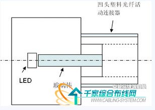
1 is a schematic diagram of the structure of an optical transmitter. The light-emitting diode (LED) is a high-brightness surface mount light-emitting diode for common display and has a driving current of less than 20 mA and a center wavelength of 590 nm (orange light). The reason why the 590nm LED is chosen is because the LED of this wavelength is very cheap, and the loss value of the plastic fiber is relatively low at the wavelength of 590 nm. The size of the LED chip is about 1.0mm×1.0mm, which is equivalent to the diameter of the plastic fiber, and it is easy to couple the optical signal into the plastic fiber.

Figure 1 is a schematic diagram of the structure of an optical transmitter

  The external input TTL level signal is FSK frequency modulated, and the TTL level signal is converted into a carrier signal more suitable for plastic optical fiber transmission to drive the LED illumination. The light signal from the light-emitting diode (LED) is directly coupled into a glass rod of 1.0 mm diameter, which is then coupled into a plastic optical fiber having a diameter of 1.0 mm through a glass rod.

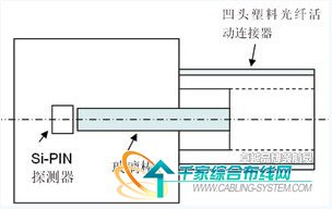
2 is a schematic diagram of the structure of the optical receiver. The photodetector detects the optical signal and generates an induced current, and then is amplified by the amplification module in two stages, and is input to the FSK demodulation module to be demodulated by the flip-flop. The demodulated signal still contains high-frequency interference, which is filtered by the filter module and then judged by the decision module to be restored to the input TTL signal.

Figure 2 Schematic diagram of the optical receiver structure

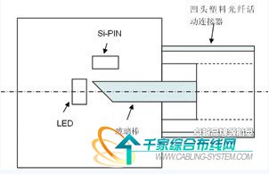
  Both of these plastic fiber optic transceiver solutions are targeted for point-to-point connections. The transceiver of the bus type plastic optical fiber communication system should be a bus type. In the photoelectric conversion, the bus type plastic optical fiber communication transceiver and the point-to-point type plastic optical fiber communication transceiver are the same, but the bus type plastic optical fiber communication transceiver is half duplex. In the mode of operation, it has only one optical signal input/output port, or it has only one concave plastic optical fiber movable connector. At this time, the glass rod of the concave plastic optical fiber movable connector is connected with the LED and the Si-PIN. The end face is not a vertical way, but a 45° bevel, so that the beam can be split into two, one way to Si-PIN, all the way to the LED. Figure 3 is a schematic diagram of a bus type of plastic optical fiber communication transceiver.

Figure 3 bus type plastic optical fiber communication transceiver

    Plastic fiber optic patch cord

Plastic fiber optic patch cords are used to connect plastic fiber optic transceivers to plastic fiber optics by coupling optical signals into plastic fibers. Similar to cable connectors, it is divided into two types: concave head and convex head. The recessed plastic optical fiber active connector and the plastic optical fiber communication transceiver are integrated, and the male plastic optical fiber connector is connected to the plastic optical fiber.

The mechanical structure of the plastic optical fiber movable connector can be variously selected. Because the diameter of the plastic optical fiber core is large, the plastic optical fiber movable connector and the currently used quartz optical fiber movable connector can be completely different, and can follow the structure of the current cable connector ( Such as SMA structure), not only the connection loss is small, but also the use of wire clamps and electrician blades, it is convenient to complete the assembly of plastic optical fiber movable connector parts in the field.

    Plastic optical fiber fixed connector

Plastic fiber optic fixed connectors are used for the connection of plastic and plastic fibers. Using a V-groove structure, two plastic optical fibers are placed in a V-shaped groove, and the plastic optical fiber is fixed by a metal material, and then a heat-shrinkable sleeve is packaged to complete the fabrication of a plastic optical fiber fixed connector. The V-groove structure can achieve the purpose of quickly and easily making a plastic optical fiber fixed connector, and the connection loss is not large due to the large diameter (1 mm) of the plastic optical fiber.

   Plastic optical bus branch

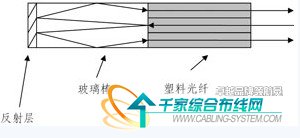
Plastic fiber optic bus splitters are used in bus-type plastic fiber optic communication systems. As shown in Fig. 4, the optical input signal of any one port is evenly distributed to other ports after being totally reflected by the glass rod and reflected by the end face of the glass rod. The requirement for the plastic optical fiber bus splitter is that the additional loss is low, the second is that the uniformity of each port is good, and the third is that the structure is simple and the cost is low.

Figure 4 plastic optical fiber bus splitter

    Plastic fiber optic light multimeter

The plastic optical fiber multimeter consists of a light source, an optical power meter, a microprocessor, and a liquid crystal display. The LED is used as the light source and the Si-PIN is used as the detector. It is similar to the fiber optic multimeter currently in use, except that the wavelength range of light used is different and the cost is different.

Key Technology Low-Cost Plastic Optical Fiber Communication Transceivers Plastic optical fiber communication transceivers should be high-sensitivity, bursty receivers and extremely low-cost fiber optic transceivers. The principle of the plastic optical fiber communication transceiver is relatively simple, but requires the circuit cost to be extremely low, and also ensures high receiving sensitivity, high reliability, and small size. At present, the system has realized the transmission sensitivity of the transmitting end -10dBm, and the receiving sensitivity of the receiving end is -40dBm (10E-9 error rate).

    Plastic fiber optic patch cord

The key technology of the plastic fiber optic patch cord is that it is simple to manufacture and low in cost. It can be easily assembled on site by using simple tools such as wire clamps and electrician blades. Its connection loss is less than 1dB.

Plastic Optical Fiber Bus Splitter The plastic optical fiber bus splitter is a key component for implementing a bus-type plastic optical fiber communication system. The optical input signal of any one port is evenly distributed to other ports.

It seems to be the 1×N optical splitter that is commonly used nowadays. In fact, the principle and function are different. A 1×N optical splitter distributes the optical input signal of one port evenly to other ports or concentrates the optical input signals of N ports onto one port, and the plastic optical fiber bus splitter requires any port. The optical input signal is evenly distributed to other ports. It is a half-duplex device. In the normal operation of the bus-type plastic optical fiber communication system, only one port has an optical signal output, and the remaining ports are input optical signals. It is used in conjunction with a bus-type plastic optical transceiver to form a bus-type plastic optical fiber communication system. It not only requires a simple structure but also requires a low cost.

Original Article Source http://cabling.qianjia.com/html/2009-09/09_192636.html

Posted on Leave a comment

The importance of using fiber optic color codes in data centers

Using fiber optic color codes in the data center can effectively help technicians better manage fiber optic cables and reduce human error. Workers can easily obtain information about the device by viewing the cable color code, which simplifies the redundant inspection process. Making full use of the optical cable color coding system can save a lot of working time. The widely accepted color coding system and its important functions are described below.

  Introduction to Cable Color Code System

Fibers, bundles, and straps in fiber optic cables are often labeled with different color codes for easy identification. Many countries use this color code system. All of these systems are characterized by the use of 12 different colors to identify fibers that are gathered together in a common bundle, such as bundle tubes, drawstrings, yarn rolls, or other types of bundles.

Different countries and regions use different color code standards. For example, in Sweden, the S12 standard is used for micro cables and nanocables. The Type E standard is defined by Televerket and Ericsson used in Sweden. Countries such as Finland use the FIN2012 standard, but a color coding system generally accepted in the world, namely the TIA/EIA-598 standard.

TIA/EIA-598 color code specifications The following figure shows the cable color coding for the TIA/EIA-598 standard. If more than 12 fibers or bundles are to be distinguished, the color sequence is usually repeated on the fibers and bundles with ring marks or lines. As for the cable jacket, the orange, yellow, light green and black color scales are used for distinguishing.

The role of the cable color code in the data center

(1) Differentiating the cable grade

As mentioned above, the outer jacket color code can identify the cable grade. The OM1/OM2 cable is usually orange-sheathed, the OM3/OM4 cable is light green, the single-mode cable is yellow, and the hybrid cable (indoor/outdoor and outdoor cables) is black. One thing to note is that mixing OM1 and OM2 or OM3 and OM4 cables can be cumbersome to handle.

(2) Identify the fiber jumper

Marking fiber patch cords with color codes can reduce the possibility of human error. For example, a mission-critical jumper can be highlighted in red and the technician can be shown that the red jumper can only be moved with proper authorization or supervision. Again, the color of the fiber optic connector needs to be consistent with the fiber-level color standard, which will make it easier for technicians to use the correct connector on the fiber optic cable.

(3) Differentiating different ports

Color-coded port icons help identify different network routes based on internal requirements. Network management can be simplified by marking each patch panel port.

(4) Distinguishing Connector Sheaths

Staff can use color codes on the boot connectors to help technicians maintain proper parallel grouping of switch ports, making routine maintenance, movement, additions, and changes easier. If you change the connector color, you need to make sure that the cable color represents the fiber grade to avoid confusion. Workers can also change the color of the boot connector to differentiate between different deployments of the optical network, allowing technicians to easily view the contrast within the panel.

Conclusion

Visual management is more intuitive for experts who manage and maintain data centers. The fiber color code provides an ideal and easy way to solve fiber routing problems. Inside the cable, the fiber buffer can also be color coded in standard colors for easy connection and splicing. Therefore, if people are still plagued by problems such as fiber jumpers, it is a good idea to use fiber color code systems.

Edit: Harris

Original Article Source http://www.jifang360.com/news/2019412/n6592117478.html

Posted on Leave a comment

Optical Fiber Types

There are two classes of Optical Fiber:
Single-Mode Fiber: generally called SMF, it is used for long distance communication
Multi-Mode Fiber: generally called MMF, it is used for short distances less than 500 meters
The advantage of MMF is that it is cheaper than SMF, and multimode connectors are cheaper and easier to terminate reliably in the field.

In recent years, there are new optical cables called active optical cables (AOC). These have the optical electronics already connected, eliminating the connectors between the cable and the optical transceiver. They will plug into standard optical transceiver sockets. Because of the manufacturer can match the electronics to the required length and type of cable, the cost of these new active optical cables is lower than other optical solutions, therefore more and more applications are deployed.

There are different types of fiber optic fiber depending on the type of network and transfer distances:
10GBASE-SR – a port type for short range multimode fiber that covers the following distances based on the grade of optical fiber cabling:
FDDI -62.5 microns, reach of approximately 26 meters
OM1 62.5 microns – a reach of approximately 33 meters
OM2 50 microns – a reach of approximately 82 meters
OM3 50 microns – a reach of approximately 300 meters
OM4 50 microns – a reach of approximately 400 meters
In fact, most of the implementations prefer to OM3 and OM4 for fiber optical cabling to longer transfer distance.
10GBASE-LR: a port type for long range single-mode fiber, supports the reach of approximately 10 kilometers (6.2 miles).
10GBASE-LRM: a port type for long range multi-mode fiber, supports distances up to approximately 220 meters.
10GBASE-ER: a port type for extended reach single-mode fiber, supports the reach of approximately 40km.
10GBASE-ZR: a port type for non-standard extended reach single-mode fiber, supports the reach of approximately 80km.
10GBASE-LX4: a port type for multimode fiber and single-mode fiber, supports reach of approximately 300 meters (980 ft) over FDDI-grade, OM1, OM2, and OM3 multi-mode cabling and 10 kilometers ( 6.2 miles ) over SMF.
SFP+ Direct Attach
Also known as 10G SFP+ Cu, 10GBase-CR, or 10GBase-CX1, SFP+, or 10GbE Cu SFP cables.

SFP+ Direct Attach Cable uses a copper 10GbE cable that comes as active or passive twin-ax cable assembly and connects directly into an SFP+ housing.

Active cables are copper cables that have a silicon chip to boost the performance of the cable. Without a chip, the cable is considered a ‘passive’ cable. Passive cables are more susceptible to degradation due to attenuation and crosstalk. This active boosting allows cables to be more compact, thinner, longer, and transmit data faster than their passive equivalents.

SFP+ Direct Attach Cable has a fixed-length cable, typically 3, 5 or 7m in length, and like 10GBASE-CX4, is low power, low cost and low latency with the added advantages of using less bulky cables and of having the small form factor of SFP+.

Passive = 1, 3, 5 Meters
Active = 7, 10,12,15 Meters

Original Article Source https://www.optcore.net/optical-fiber-types/

Posted on Leave a comment

How to organize the fiber jumpers in the cabinet

How to organize the fiber jumpers in the cabinet

1 Steps for skipping content:

The first step: identify the light and the room, find the splitter.

Step 2: Identify the splitter number.

Step 3: Find the splitter port configured on the work order.

Step 4: Find the port of the cable core of the access user.

Step 5: Jump from the splitter port to the user cable port.

2 Basic knowledge and specifications of fiber jumper:

1) The fiber-optic operation must meet the principles of ODF frame, light communication, tidy inside the integrated box, beautiful wiring, easy operation, and less space.

2) The length of the jumper must be within the range of 500mm.

3) Jumpers of insufficient length shall not be used. It is not allowed to use flanges to connect two jumpers.

4) Each jumper should ensure that the radius of curvature is greater than 400mm.

5) General requirements for fiber removal:

1 For the fiber on the upper line, the cable should be off the outside of the ODF frame. Select the most suitable fiber column for the remaining fiber volume, and move the fiber upwards on the inside of the ODF frame. The horizontal edge is on the lower edge of the ODM and is perpendicular to the corresponding terminal.

2 One jumper is only allowed to go up once in the ODF frame (along the outside of the ODF frame), once on the side (along the inside of the ODF frame), and take a fiber column. It is forbidden to entangle, cross and hang between the multiple fiber columns. That is, there must be no filament winding on the upper edge of each disc.

3 The specific situation of the site should be stipulated after the initial preparation of the jumper.

4 All jumpers must be placed in the ODF frame. It is strictly forbidden to deploy outside the aircraft and fly the line.

5 The super long jump fiber for emergency use shall be hung on the inner fiber disc according to the rules, and shall not affect the future fiber jump.

3 Jumper type and length control

1) Select the corresponding  SC-SCfiber jumper, FC-FCfiber jumper, SC-FCfiber jumper according to the flange head on the splitter and the splitter box.

2) The fiber jumper from the splitter to the user table, the length of the length is controlled within 50CM, and the pigtails of 1m, 2m, 2m5, 3m are generally selected.

3) The ONU and the fiber terminal jumper in the user terminal box generally use 50CM short pigtail.

4 Jumper label management and specification

1) All jumper labels must be labeled with the machine and no handwriting is allowed.

2) In the machine room, light communication, and corridor, the fiber-optic to the user’s leather cable must be attached to both ends of the fiber-optic cable.

3) The effect after completion is uniform specification length, according to the gap of the terminal position, the labels are not staggered.

4) The front side is the name of the light path, and the reverse side is the light path code and barcode, and the orientation is uniform.

5) The change text hangs down with the pigtails, naturally facing up.

5 Perform the necessary optical path test

After each fiber path jump is completed, it needs to be tested. The test steps are as follows:

1) Test the wavelength of the splitter at 1490 with an optical power meter, and the optical power should be less than -22dB.

2) The user end tests with the 1490 wavelength of the optical power meter. The receiving power should be less than -23dB, and the maximum sensitivity of the ONU is generally -24dB.

3) Use the ONU device to debug the Internet for the user.

4) If there is no light, you can judge whether the fiber is wrong by the visible light source (red light).

5) If there is no fiber but still no light, when the loss is large, the ONU can not work normally, and the cable maintenance department can be informed.

6 Resource Management

It is strictly forbidden to change the fiber order of the construction sheet without authorization. The optical path resources need to be changed during the loading and maintenance process. The relevant information of the optical path is recorded on the work order and timely reported to the resource department for updating.

The above are all the techniques for dust removal in the cabinet and how to organize the fiber jumper in the cabinet. In fact, the cabinet can be extended by cleaning, and the fiber jumper in the cabinet is arranged to facilitate our future inspection and aesthetic effect.

Disclaimer: All information indicated as other sources is transferred from other platforms, the purpose is to convey more information, does not represent the views and positions of this site. Please contact us if there is any infringement or objection.

Posted on Leave a comment

How to manage the optical fiber jumper of the integrated wiring system

In general, reasonable jumper management can be divided into five phases: planning, preparation, wiring, testing, and verification.

1 jumper operation specification

1.1 plan

Pre-establishment, no pre-emptive, and doing everything in advance requires detailed planning in advance. For jumper management, you should plan your current and future needs.

(1.1.1) Change request. Various management activities, moves, additions, or changes (MACs) begin with a change request. The change request must contain all the necessary information to start the planning process.

(1.1.2) Search records. After receiving the request form, the record should be searched to determine the circuit path used.

(1.1.3) Correct routing. Before determining the correct jumper length, first, find the best route between the ports to be connected. It is usually the shortest path through the horizontal and vertical cable conduits and must not obstruct or obstruct other jumpers or connectors in the patch panel. Select jumpers, avoid excessive slack and ensure a neat appearance. Too tight a jumper will increase the tension on the connector, and excessive slack will cause trouble for jumper management and increase the management difficulty of the patch panel.

1.2 Preparation

After making the plan for jumper management, you should follow the plan prepared in advance, and then you should prepare for the jumper management. Prepare as much as possible before conducting management operations to study management records. Determine the location of the port that needs to be connected and reconnected and the label information of the relevant port.

(1.2.1) First, check the model that requires the jumper, and then check the quality of the jumper. In order to ensure that the quality of the jumper is correct, it is necessary to check whether the jumper is damaged. In order to check whether it is damaged, you can first check it from the appearance of the jumper. If you have the condition, you can check it with a professional instrument.

(1.2.2) Next, check the condition of the joint to avoid physical damage to the joint.

(1.2.3) Finally, it is necessary to clean the jumper connector and the connection part.

There are two methods for cleaning the fiber optic connector: contact and non-contact:

Contact cleaning method:

(1) Wiping paper and anhydrous alcohol, using original wood pulp with special processing technology, ultra-low dust, pure texture, high-efficiency water absorption, fine paper, will not scratch the surface of the inserted object, use low dust wipe paper with no Water alcohol wipes the fiber optic connector;

(2) Non-woven fabric, no lint, strong, no chemical impurities, silky soft, does not cause allergic reactions and is not easy to fluff and hair loss, is produced or tested as a fiber optic connector or pin Ideal for cleaning wipes, wipe the fiber optic connector with anhydrous alcohol during use.

(3) Cleaning cotton swabs, specially designed for internal cleaning of ceramic bushings, or for cleaning ferrule end faces that are not easily accessible in flanges (or adapters);

(4) Professional cleaners, special cleaners for fiber optic connectors use a special role of wiping tape, which can be installed in a rollable casing without alcohol. Each cleaning is very effective and produces a new surface, which is convenient and practical.

Non-contact method:

(1) Ultrasonic cleaning method, which turns the cleaning liquid into an ultrasonic “liquid column” and sends it to the end face of the connector, and recovers and absorbs the waste liquid in the same small space;

(2) High-pressure blowing method, the principle is that the cleaning liquid is first applied to the end face of the connector, and then the high-pressure gas is used to align the end face of the connector;

(1.2.4) Check the cleaning of the fiber connector

After cleaning the fiber optic connector, the termination faces must be inspected. The general practice is to use a magnifying glass of 100, 200 or 400 times. The figure below shows the state of the fiber termination surface in a clean state and after being contaminated.

Jumper managers, no matter what method is used, are difficult to clean for some heavily contaminated connectors and need to be treated with a cleaning solution such as cotton swabs and alcohol.

After this series of preparations, it means that the wiring work of the jumper management can be carried out.

1.3 wiring

The installation of the distribution frame shall be completed at various stages in accordance with the operating procedures. Kink knots, burrs, pinches, and poor contact in jumper construction can significantly reduce jumper performance. To avoid such problems, the following factors should be considered:

(1) Bending radius

The minimum bend radius allowed for the jumper is subject to the jumper manufacturer’s specifications.

The standard stipulates that the minimum bend radius of unshielded twisted pair (UTP) should be four times the diameter of the cable, and the shielded twisted pair is eight times the diameter of the cable. The minimum bend radius of a 2-core or 4-core horizontal cable is greater than 25 mm. If the bend radius is less than this standard, the relative position of the wire may be changed, resulting in a decrease in transmission performance.

(2) Jumper stretching and stress

During the wiring process, do not use excessive force, otherwise, the stress on the jumper and the connector may be increased, resulting in performance degradation.

(3) Bundling

Jumpers do not necessarily need to be bundled. If the strapping needs to comply with the manufacturer’s strapping principle, do not bundle too tightly, otherwise, it will cause the twisted pair to be deformed. Do not overtighten the clamps. It is advisable to rotate the jumpers freely. Use a dedicated product and consider a product that can be used repeatedly without tools, such as a Velcro tape.

1.4 test

(1) Although it has been completed by jumper wiring, it may not be considered whether the fiber link or copper link fully complies with the operating specifications or the international standard of the integrated wiring, then the fiber or copper cable test should be carried out. After the test standard is met, it can be determined whether the test standard has passed.

1.5 verification

(1) It is worthwhile to spend some time on the final visual inspection of the connection. Make sure that the jumper is not kinked and is not caught by the cabinet door.

(2) The last step is to update the record according to the current configuration and close the work order related to the changed request that has been executed.

Jumpers are now an important part of the cabling system, especially for the good management of jumpers in data center projects. It is believed that as long as the construction management personnel correctly and reasonably jumper management operations, the entire integrated wiring will become a truly advanced, scientific, practical, and reliable system.

Disclaimer: All information indicated as other sources is transferred from other platforms, the purpose is to convey more information, does not represent the views and positions of this site. Please contact us if there is any infringement or objection.

Posted on Leave a comment

what are the types of fiber jumpers?


what are the types of fiber jumpers?

(1) Classification by fiber type

1. Single mode fiber patch cord: generally yellow, the connector and protective cover are blue, and the transmission distance is long.

2. Multimode fiber patch cord: generally orange or water blue, the connector and protective cover are beige or black, and the transmission distance is short.

(2) Classification by connector type

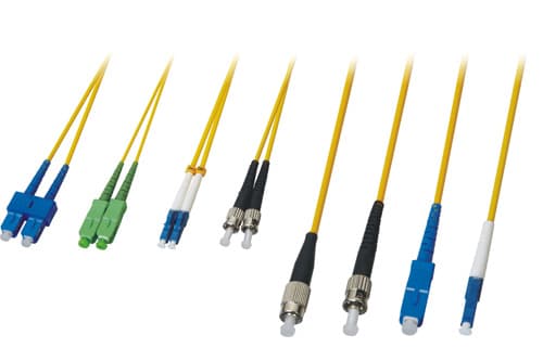
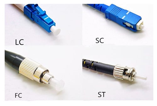
Fiber patch cords can be classified into FC, ST, SC, LC, MU, E2000, MTRJ, SMA, etc. according to the connector. The following is a detailed description of commonly used fiber jumpers:

1. FC fiber jumper

The FC (Ferrule Connector) fiber patch cord is one of the most common connected devices in a single mode network. Its external reinforcement method is a metal sleeve, and the fastening method is a turnbuckle. Common on the ODF side (most seen on the patch panel). The FC connector is generally used in a large number of telecommunication networks. Its advantage is that it is reliable and dust-proof. The disadvantage is that the installation time is slightly longer.

2. ST fiber jumper

ST (Stab & Twist) fiber patch cords are the most common connection devices in multimode networks and are the more common types of connectors in Base10 fiber connections. Often used on fiber distribution frames. The outer casing is round, and the fastening method is a turnbuckle. The core is exposed, and it needs to be inserted first, and then the half-cycle fixed bayonet is rotated.

3. SC fiber patch cord

The SC (Square Connector) fiber patch cord is a TIA-568-A standardized connector. It was not widely used at an early stage due to its high price. It was gradually used in connection with GBIC optical modules due to its excellent performance. Commonly found on router switches, the outer casing is rectangular, and the fastening method is plug-and-pull type. Unlike ST/FC, it does not need to be rotated.

4. LC fiber patch cord

The LC (Lucent connector) fiber patch cord is usually connected to the SFP optical module. The connector is similar to the SC connector but smaller than the SC connector. The size of the pin and the sleeve is 1.25mm, which is half of the ordinary SC and FC. The fastening method is the jack latch. Its advantages and performance are good, which can improve the density of the fiber connector in the fiber distribution frame to a certain extent, and is a good single mode fiber jumper.

(3) Classification by application of jumpers

Optical fiber jumpers are generally classified into MTP/MPO fiber jumpers, conventional fiber jumpers, and armored fiber jumpers.

1. MTP/MPO fiber jumper: It is common in a fiber-optic line environment where high-density integration is required in the wiring process. Its advantages are: easy to install and remove, save time and cost, and maximize the service life.

2. Armored fiber optic patch cords: Common in the machine room, suitable for use in harsh environments. Its advantages: no need to use protective casing, can prevent moisture and fire, have antistatic and acid and alkali resistance, can save space and reduce construction cost.

3. Conventional Fiber Patch Cables: Conventional Fiber Patch Cables are OS2 9/125 Single Mode Simplex, OM4 40/100Gb 50/125 Multimode, OM3 10Gb 50/125 Multimode, OM2 50/125 Multimode, OM1 62.5/125 Multimode, OS2 9/125 single mode simplex, OM5 50/125 multimode these types.

Among them, OM5 fiber patch cord is a popular product, which is often used for higher bandwidth. The outer sheath is water green, with strong scalability, compatibility, and interoperability, which can effectively reduce costs.

Disclaimer: All information indicated as other sources is transferred from other platforms, the purpose is to convey more information, does not represent the views and positions of this site. Please contact us if there is any infringement or objection.

Posted on Leave a comment

Transport network prepared for 5G: Fiber is the future of 5G

It is reported that the theme of this year’s MWC and OFC conference is to prepare the transmission network for the upcoming 5G. The current industry consensus is that 2020 will begin to deploy 5G extensively. But because 5G NR is still in the early stages of standardization, 5G preparation is also a tricky issue.

 
  With the continuous changes of the 5G wireless standard, what measures can network operators take now to lay the foundation for the 5G transmission network? The good news is that at least the 5G road at the physical layer is clear: the optical fiber will be the basis of the 5G network, centralized The RAN (C-RAN) will become the 5G network architecture.

C-RAN was introduced through 4G (commercial deployment is now expanding) and adds a new transport segment to the mobile network: go. After the C-RAN is used, the radio units remain in the base station tower, but the baseband processing units (BBUs) move from the unit tower to the central office to enable communication with each other and with other components. Using the standard CPRI protocol, the distance between the base station tower and the BBUs can be as much as 20 kilometers.

C-RAN has two main points: 1) C-RAN is the transport network architecture required for 5G because the virtualization of BBUs (Cloud RAN) will become a key component for implementing 5G. In order to expand and implement virtualization, the C-RAN architecture needs to be implemented immediately; 2) Due to the combination of capacity and distance requirements, the outbound network will be primarily based on fiber.

The physical layer test requirements are also very simple, with a focus on testing the fiber characteristics that are critical to any fiber network. That is to say, there are some differences when preparing the 5G data rate and architecture.

attenuation

Attenuation is the reduction in power of an optical signal as it propagates through the fiber. Common causes of attenuation include poor connector quality, tight fiber bending, faulty fiber splices, and defects in the fiber itself due to increased transmission distance. Compared with distributed RAN, C-RAN introduces two important factors that may increase loss: 1) Larger fiber transmission distance – physical separation distance between the remote headend and BBUs increases from tens of meters of distributed RAN Up to 10 km to 20 km; 2) A larger number of connectors in the transmission route.

The Optical Time Domain Reflectometer (OTDR) is the correct test tool for accurate attenuation measurement and should be performed on any new C-RAN fiber installation. If the OTDR point connector has an abnormally high loss, the inspection probe helps determine if the fiber end face should be cleaned.

Chromatic dispersion & polarization mode dispersion

Dispersion is an extension of the light pulse and may result in an increase in the bit error rate in optical transmission. The two most important forms currently are chromatic dispersion (CD) and polarization mode dispersion (PMD). The CD is caused by different wavelengths (colors) in the light pulses operating at different speeds, and the PMD is caused by the difference in propagation speeds of different polarization states.

At the sub-10G rate, the CD and PMD tolerances are very high; however, at 10G and above, dispersion becomes a problem. This is an important consideration because mobile backhaul networks can achieve data rates of 10 Gbps (and eventually higher).

In addition, distance is also a factor. Test and measurement supplier EXFO recommends dispersion testing for any span greater than 15 km to 20 km; these tests are performed prior to commissioning to avoid CD/PMD related failures.

The migration of coherent 100G transmissions in remote networks and in metropolitan area networks has reduced many problems with dispersion impairment due to the function of digital signal processing.

However, coherent detection introduces some limitations that are not present in 10G direct detection systems, such as sensitivity to rapid changes in polarization state (SOP) and PMD. Since SOP and PMD can change in a few microseconds, coherent receivers must compensate PMD and SOP in real time; but if they change too fast, sometimes they are not implemented, resulting in signal loss.

The best way to prevent SOP and PMD compensation faults in coherent receivers is to avoid using fibers with higher PMD because SOPs and PMDs change more frequently in higher PMD fibers.

In summary, for operators planning the future of 5G, it is now possible to take measures at the physical layer to extend the fiber to its cell site in anticipation of the need for a centralized RAN architecture at a higher level. From a physical layer test point of view, the method is simple and will focus on fiber characteristics.

Disclaimer: All information indicated as other sources is transferred from other platforms, the purpose is to convey more information, does not represent the views and positions of this site. Please contact us if there is any infringement or objection.