Posted on Leave a comment

How to choose data center MPO/MTP high-density fiber pre-connection system?

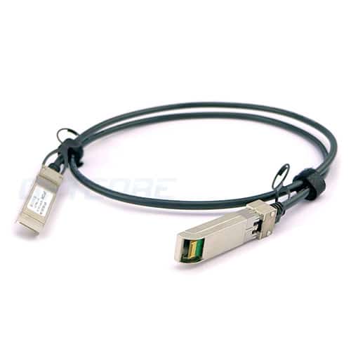
Mobile communication network news, MPO/MTP high-density optical fiber pre-connection system is currently mainly used in three areas: high-density environment applications in data centers, fiber-to-building applications, optical transceivers in optical splitters, 40G, 100G SFP, SFP+, etc. Connection application inside the device. This article focuses on why data centers use MPO/MTP high-density fiber pre-connection systems and how to choose such high-density fiber pre-connection systems.

  Before introducing the current use of MPO/MTP high-density fiber pre-connection systems in these situations, it is necessary to make a brief introduction to MPO/MTP. In the field of communication and data transmission, the development of optical fiber connectors is far more developed than the development of copper connectors. According to incomplete statistics, so far, hundreds of fiber optic connectors have been developed, but there are more than a dozen that are actually used in a wide range. Throughout its development, fiber optic connectors have two distinct stages of development:

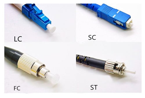
  The first stage: in order to save space and develop towards miniaturization, fiber optic connectors have evolved from traditional FC, ST, SC to LC, MTRJ, E2000

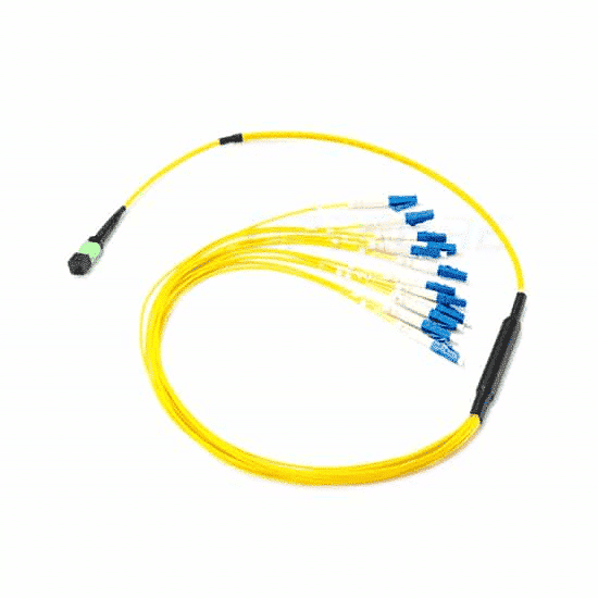
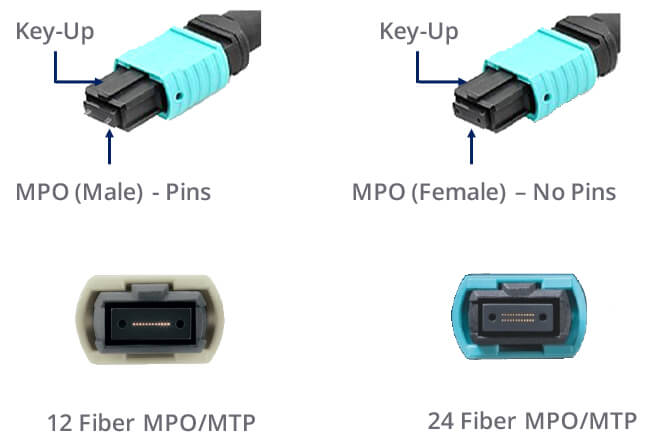
  The second stage: not only to save space but also to meet the requirements of multi-core use, fiber optic connectors evolved from LC, MTRJ, E2000 to MU, MTP/MPOFIBER CABLING, now an MTP/MPO multi-core connector can meet 2 cores, 4 cores , 8-core, 12-core, 24-core, currently up to 72 cores.

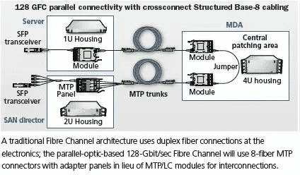
  The benefits of this development in the second phase are obvious. Look at the 40G and 100G requirements for fiber-optic network transmission specifications. Multi-core transmission, that is, 8-core or 20-core. In this way, MPO/MTP FIBER CABLING can meet the requirements of high-speed network applications in a small space. However, engineers who work on the site also bring great challenges and even impossible tasks. Of course, there is now a good alternative, which is the pre-connected system of the manufacturing plant.

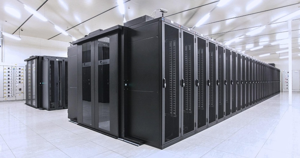
  The application of the MPO/MTP fiber pre-connection system in the data center has also been a matter of the past few years, and it is also the most important application of the MPO/MTP pre-connection system in China. The reason is not as noble as imagined, but it is actually an inevitable choice. Let me talk about the first reason: the data center space is always not enough. Just like the completion of Beijing’s subway for half a year, passenger traffic is full. This is actually a contradiction between limited resources and unlimited demand. This phenomenon is manifested in various fields in China today. To solve the problem of insufficient space, you can increase the space or increase the utilization of space. It is unrealistic to increase space in a designed data center. Increasing the space utilization rate means increasing density. As the two major wiring systems in the data center: copper cables, cable cabling systems, in fact, copper systems can also use high density, but this high-density space savings are limited. Because it is not only impossible to find a balance between the high frequency and the larger line; the electrical transmission performance of the cable at high frequency is not easy to meet, and the high-frequency electronic signal is also transmitted in the multi-core copper transmission. A series of questions. Of course, in order to install a convenient copper pre-connection system on site, this is another topic, no matter here. Therefore, in order to get more transmission bandwidth in the same space, switching to optical cable transmission is an inevitable choice, but this does not mean that a high-density optical fiber pre-connection system is required.

Original Article Source  https://www.mscbsc.com/viewnews-94461.html

Posted on Leave a comment

How to organize the fiber jumpers in the cabinet

How to organize the fiber jumpers in the cabinet

1 Steps for skipping content:

The first step: identify the light and the room, find the splitter.

Step 2: Identify the splitter number.

Step 3: Find the splitter port configured on the work order.

Step 4: Find the port of the cable core of the access user.

Step 5: Jump from the splitter port to the user cable port.

2 Basic knowledge and specifications of fiber jumper:

1) The fiber-optic operation must meet the principles of ODF frame, light communication, tidy inside the integrated box, beautiful wiring, easy operation, and less space.

2) The length of the jumper must be within the range of 500mm.

3) Jumpers of insufficient length shall not be used. It is not allowed to use flanges to connect two jumpers.

4) Each jumper should ensure that the radius of curvature is greater than 400mm.

5) General requirements for fiber removal:

1 For the fiber on the upper line, the cable should be off the outside of the ODF frame. Select the most suitable fiber column for the remaining fiber volume, and move the fiber upwards on the inside of the ODF frame. The horizontal edge is on the lower edge of the ODM and is perpendicular to the corresponding terminal.

2 One jumper is only allowed to go up once in the ODF frame (along the outside of the ODF frame), once on the side (along the inside of the ODF frame), and take a fiber column. It is forbidden to entangle, cross and hang between the multiple fiber columns. That is, there must be no filament winding on the upper edge of each disc.

3 The specific situation of the site should be stipulated after the initial preparation of the jumper.

4 All jumpers must be placed in the ODF frame. It is strictly forbidden to deploy outside the aircraft and fly the line.

5 The super long jump fiber for emergency use shall be hung on the inner fiber disc according to the rules, and shall not affect the future fiber jump.

3 Jumper type and length control

1) Select the corresponding  SC-SCfiber jumper, FC-FCfiber jumper, SC-FCfiber jumper according to the flange head on the splitter and the splitter box.

2) The fiber jumper from the splitter to the user table, the length of the length is controlled within 50CM, and the pigtails of 1m, 2m, 2m5, 3m are generally selected.

3) The ONU and the fiber terminal jumper in the user terminal box generally use 50CM short pigtail.

4 Jumper label management and specification

1) All jumper labels must be labeled with the machine and no handwriting is allowed.

2) In the machine room, light communication, and corridor, the fiber-optic to the user’s leather cable must be attached to both ends of the fiber-optic cable.

3) The effect after completion is uniform specification length, according to the gap of the terminal position, the labels are not staggered.

4) The front side is the name of the light path, and the reverse side is the light path code and barcode, and the orientation is uniform.

5) The change text hangs down with the pigtails, naturally facing up.

5 Perform the necessary optical path test

After each fiber path jump is completed, it needs to be tested. The test steps are as follows:

1) Test the wavelength of the splitter at 1490 with an optical power meter, and the optical power should be less than -22dB.

2) The user end tests with the 1490 wavelength of the optical power meter. The receiving power should be less than -23dB, and the maximum sensitivity of the ONU is generally -24dB.

3) Use the ONU device to debug the Internet for the user.

4) If there is no light, you can judge whether the fiber is wrong by the visible light source (red light).

5) If there is no fiber but still no light, when the loss is large, the ONU can not work normally, and the cable maintenance department can be informed.

6 Resource Management

It is strictly forbidden to change the fiber order of the construction sheet without authorization. The optical path resources need to be changed during the loading and maintenance process. The relevant information of the optical path is recorded on the work order and timely reported to the resource department for updating.

The above are all the techniques for dust removal in the cabinet and how to organize the fiber jumper in the cabinet. In fact, the cabinet can be extended by cleaning, and the fiber jumper in the cabinet is arranged to facilitate our future inspection and aesthetic effect.

Disclaimer: All information indicated as other sources is transferred from other platforms, the purpose is to convey more information, does not represent the views and positions of this site. Please contact us if there is any infringement or objection.

Posted on Leave a comment

How does the switch choose the correct branch jumper?

       This article will serve as the best guide for MTP-to-LC branch jumpers for structured cabling applications, focusing on 12- and 8-core MTP-to-LC branch jumper cables for LAN and LAN switches from different vendors. Worker light port.

  What is the MTP-LC branch jumper?

  A branch jumper is a fiber optic cable assembly with a multi-core MTP connector on one end and an outer jacketed branch with a single or dual core LC connector on the other end. It provides a conversion for the backbone of the MTP connector, the backbone extension cable or the back of the single/dual connector module. Figure 1 shows an example of some differently constructed branch jumpers.

      What are the benefits of using the MTP-LC branch jumper?

  When designing a network system, it is very important to plan the structured cabling in advance. Our goal is to address the current network needs and adapt to future growth. Structured cabling systems have the flexibility to handle the usual execution moves, adding or changing infrastructure tasks, along with the evolution of the network. Using MTP-LC branch jumpers in high-density LAN or storage switches can help you improve structured cabling.

  Use the branch jumper component to compare some of the main advantages of traditional jumpers:

  1. Branch jumpers provide a clean, high-density approach to high-density switch port replication, which reduces the risk of port corruption or errors on the switch.

  2. The branch jumper occupies less space in the cabinet and has better vertical management than the traditional jumper. The branch at one end of the 12-core branch jumper is much smaller than the jumper with an equal number of cores.

  3. Reduce cable congestion for LANs and storage networks; improve airflow for increased cooling and make moving, adding and changing easier (mac).

  4. The branch jumper provides a network port that can be used to include an engineered interleaved LC branch to match the electronics to provide seamless integration between the cabling infrastructure and the electronic device.

  What is the typical application of the MTP-LC branch jumper?

  The MTP-LC branch jumper is used for port replication of the blade switchboard to facilitate connection of these ports to other devices. There are two types of branch jumpers, module branch jumpers, and trunk branch jumpers based on the specific application and which components are plugged in.

  The module branch jumpers are connected directly to the rear of the MTP-LC module, copying the switch ports to the patch panels located in the same or adjacent racks. When this application is typically used, the switch is in MDA or column header switching. Figure 2 depicts an example of a module branch jumper application.


  The switch-mapped patch panel is located outside of the switch’s location. Deploying this application is usually the main distribution area (MDA) required when you have a common switch area and port replication. Figure 3 depicts an example of a trunk branch jumper application.


  What LC branch length should I use for the MTP-LC branch jumper?

  The optimal branch jumper LC branch length will depend on the following factors: chassis model, blade type, number of blade ports, port direction, and routing. This article provides customized staggered branch jumpers for different industry vendors to match the ports of each of their data center switch product lines, providing seamless integration between cabling infrastructure and electronics.

  Staggered types 1, 2, 3, and 5 are precisely designed lengths that are specifically matched to the layout of switch ports at different vendors. In addition, this article provides a variety of uniform length/non-staggered branch lengths (eg, 6 inches (staggered type 4 branches), 12 inches, 24 inches, and 36 inches) depending on your wiring needs. Figures 4 and 5 show different staggered type configurations.


  Which direction of the MTP-LC branch jumper should I choose when wiring the switch?

  The best switch routing direction will depend on two factors, the direction of the blade board and the fan/intake position. For example, if your switch is a horizontal blade card and fan/air intake position, it does not prevent the branch jumper from coming left or right, which can be attributed to customer preferences. On the other hand, if the fan/intake is on one side of the switch, you should route your branch jumper from the other side.

  The same applies to switches in the vertical blade card. This article provides an optimal routing direction for different industry manufacturers based on different switch chassis products. Figure 6 shows the different routing directions.

  With the widespread availability of switches in the networking market, there are several configurations of MTP-LC branch jumpers to choose from. The rest of this document will help you decide which branch jumpers are best for your storage network or LAN switch cabling. On the next page are Tables 1 and 2, summarizing the use of 12-core or 8-core-based branch jumpers based on switch manufacturer, module, port number, port direction, and routing direction. The part numbers for each different branch jumper type are in Tables 3 and 4. The illustrated example is a different switch/blade-mounted MTP-LC branch jumper that can be found in Appendix A. 

Disclaimer: All information indicated as other sources is transferred from other platforms, the purpose is to convey more information, does not represent the views and positions of this site. Please contact us if there is any infringement or objection.

Posted on Leave a comment

How to manage the optical fiber jumper of the integrated wiring system

In general, reasonable jumper management can be divided into five phases: planning, preparation, wiring, testing, and verification.

1 jumper operation specification

1.1 plan

Pre-establishment, no pre-emptive, and doing everything in advance requires detailed planning in advance. For jumper management, you should plan your current and future needs.

(1.1.1) Change request. Various management activities, moves, additions, or changes (MACs) begin with a change request. The change request must contain all the necessary information to start the planning process.

(1.1.2) Search records. After receiving the request form, the record should be searched to determine the circuit path used.

(1.1.3) Correct routing. Before determining the correct jumper length, first, find the best route between the ports to be connected. It is usually the shortest path through the horizontal and vertical cable conduits and must not obstruct or obstruct other jumpers or connectors in the patch panel. Select jumpers, avoid excessive slack and ensure a neat appearance. Too tight a jumper will increase the tension on the connector, and excessive slack will cause trouble for jumper management and increase the management difficulty of the patch panel.

1.2 Preparation

After making the plan for jumper management, you should follow the plan prepared in advance, and then you should prepare for the jumper management. Prepare as much as possible before conducting management operations to study management records. Determine the location of the port that needs to be connected and reconnected and the label information of the relevant port.

(1.2.1) First, check the model that requires the jumper, and then check the quality of the jumper. In order to ensure that the quality of the jumper is correct, it is necessary to check whether the jumper is damaged. In order to check whether it is damaged, you can first check it from the appearance of the jumper. If you have the condition, you can check it with a professional instrument.

(1.2.2) Next, check the condition of the joint to avoid physical damage to the joint.

(1.2.3) Finally, it is necessary to clean the jumper connector and the connection part.

There are two methods for cleaning the fiber optic connector: contact and non-contact:

Contact cleaning method:

(1) Wiping paper and anhydrous alcohol, using original wood pulp with special processing technology, ultra-low dust, pure texture, high-efficiency water absorption, fine paper, will not scratch the surface of the inserted object, use low dust wipe paper with no Water alcohol wipes the fiber optic connector;

(2) Non-woven fabric, no lint, strong, no chemical impurities, silky soft, does not cause allergic reactions and is not easy to fluff and hair loss, is produced or tested as a fiber optic connector or pin Ideal for cleaning wipes, wipe the fiber optic connector with anhydrous alcohol during use.

(3) Cleaning cotton swabs, specially designed for internal cleaning of ceramic bushings, or for cleaning ferrule end faces that are not easily accessible in flanges (or adapters);

(4) Professional cleaners, special cleaners for fiber optic connectors use a special role of wiping tape, which can be installed in a rollable casing without alcohol. Each cleaning is very effective and produces a new surface, which is convenient and practical.

Non-contact method:

(1) Ultrasonic cleaning method, which turns the cleaning liquid into an ultrasonic “liquid column” and sends it to the end face of the connector, and recovers and absorbs the waste liquid in the same small space;

(2) High-pressure blowing method, the principle is that the cleaning liquid is first applied to the end face of the connector, and then the high-pressure gas is used to align the end face of the connector;

(1.2.4) Check the cleaning of the fiber connector

After cleaning the fiber optic connector, the termination faces must be inspected. The general practice is to use a magnifying glass of 100, 200 or 400 times. The figure below shows the state of the fiber termination surface in a clean state and after being contaminated.

Jumper managers, no matter what method is used, are difficult to clean for some heavily contaminated connectors and need to be treated with a cleaning solution such as cotton swabs and alcohol.

After this series of preparations, it means that the wiring work of the jumper management can be carried out.

1.3 wiring

The installation of the distribution frame shall be completed at various stages in accordance with the operating procedures. Kink knots, burrs, pinches, and poor contact in jumper construction can significantly reduce jumper performance. To avoid such problems, the following factors should be considered:

(1) Bending radius

The minimum bend radius allowed for the jumper is subject to the jumper manufacturer’s specifications.

The standard stipulates that the minimum bend radius of unshielded twisted pair (UTP) should be four times the diameter of the cable, and the shielded twisted pair is eight times the diameter of the cable. The minimum bend radius of a 2-core or 4-core horizontal cable is greater than 25 mm. If the bend radius is less than this standard, the relative position of the wire may be changed, resulting in a decrease in transmission performance.

(2) Jumper stretching and stress

During the wiring process, do not use excessive force, otherwise, the stress on the jumper and the connector may be increased, resulting in performance degradation.

(3) Bundling

Jumpers do not necessarily need to be bundled. If the strapping needs to comply with the manufacturer’s strapping principle, do not bundle too tightly, otherwise, it will cause the twisted pair to be deformed. Do not overtighten the clamps. It is advisable to rotate the jumpers freely. Use a dedicated product and consider a product that can be used repeatedly without tools, such as a Velcro tape.

1.4 test

(1) Although it has been completed by jumper wiring, it may not be considered whether the fiber link or copper link fully complies with the operating specifications or the international standard of the integrated wiring, then the fiber or copper cable test should be carried out. After the test standard is met, it can be determined whether the test standard has passed.

1.5 verification

(1) It is worthwhile to spend some time on the final visual inspection of the connection. Make sure that the jumper is not kinked and is not caught by the cabinet door.

(2) The last step is to update the record according to the current configuration and close the work order related to the changed request that has been executed.

Jumpers are now an important part of the cabling system, especially for the good management of jumpers in data center projects. It is believed that as long as the construction management personnel correctly and reasonably jumper management operations, the entire integrated wiring will become a truly advanced, scientific, practical, and reliable system.

Disclaimer: All information indicated as other sources is transferred from other platforms, the purpose is to convey more information, does not represent the views and positions of this site. Please contact us if there is any infringement or objection.

Posted on Leave a comment

what are the types of fiber jumpers?


what are the types of fiber jumpers?

(1) Classification by fiber type

1. Single mode fiber patch cord: generally yellow, the connector and protective cover are blue, and the transmission distance is long.

2. Multimode fiber patch cord: generally orange or water blue, the connector and protective cover are beige or black, and the transmission distance is short.

(2) Classification by connector type

Fiber patch cords can be classified into FC, ST, SC, LC, MU, E2000, MTRJ, SMA, etc. according to the connector. The following is a detailed description of commonly used fiber jumpers:

1. FC fiber jumper

The FC (Ferrule Connector) fiber patch cord is one of the most common connected devices in a single mode network. Its external reinforcement method is a metal sleeve, and the fastening method is a turnbuckle. Common on the ODF side (most seen on the patch panel). The FC connector is generally used in a large number of telecommunication networks. Its advantage is that it is reliable and dust-proof. The disadvantage is that the installation time is slightly longer.

2. ST fiber jumper

ST (Stab & Twist) fiber patch cords are the most common connection devices in multimode networks and are the more common types of connectors in Base10 fiber connections. Often used on fiber distribution frames. The outer casing is round, and the fastening method is a turnbuckle. The core is exposed, and it needs to be inserted first, and then the half-cycle fixed bayonet is rotated.

3. SC fiber patch cord

The SC (Square Connector) fiber patch cord is a TIA-568-A standardized connector. It was not widely used at an early stage due to its high price. It was gradually used in connection with GBIC optical modules due to its excellent performance. Commonly found on router switches, the outer casing is rectangular, and the fastening method is plug-and-pull type. Unlike ST/FC, it does not need to be rotated.

4. LC fiber patch cord

The LC (Lucent connector) fiber patch cord is usually connected to the SFP optical module. The connector is similar to the SC connector but smaller than the SC connector. The size of the pin and the sleeve is 1.25mm, which is half of the ordinary SC and FC. The fastening method is the jack latch. Its advantages and performance are good, which can improve the density of the fiber connector in the fiber distribution frame to a certain extent, and is a good single mode fiber jumper.

(3) Classification by application of jumpers

Optical fiber jumpers are generally classified into MTP/MPO fiber jumpers, conventional fiber jumpers, and armored fiber jumpers.

1. MTP/MPO fiber jumper: It is common in a fiber-optic line environment where high-density integration is required in the wiring process. Its advantages are: easy to install and remove, save time and cost, and maximize the service life.

2. Armored fiber optic patch cords: Common in the machine room, suitable for use in harsh environments. Its advantages: no need to use protective casing, can prevent moisture and fire, have antistatic and acid and alkali resistance, can save space and reduce construction cost.

3. Conventional Fiber Patch Cables: Conventional Fiber Patch Cables are OS2 9/125 Single Mode Simplex, OM4 40/100Gb 50/125 Multimode, OM3 10Gb 50/125 Multimode, OM2 50/125 Multimode, OM1 62.5/125 Multimode, OS2 9/125 single mode simplex, OM5 50/125 multimode these types.

Among them, OM5 fiber patch cord is a popular product, which is often used for higher bandwidth. The outer sheath is water green, with strong scalability, compatibility, and interoperability, which can effectively reduce costs.

Disclaimer: All information indicated as other sources is transferred from other platforms, the purpose is to convey more information, does not represent the views and positions of this site. Please contact us if there is any infringement or objection.

Posted on Leave a comment

The next-generation data center can not ignore the DAC high-speed copper cable connection application

market background

Innovative network technologies and endless network applications are driving the rapid development of the network. As a data center for centralized processing of information data and storage of network equipment, it has been facing the challenges of high bandwidth, high reliability, and low latency. According to the IDC Industry Development Research Report, as of 2011, the global IDC market maintained a steady growth trend. The overall market size reached US$22.26 billion, with a growth rate of 21.5%. Among them, emerging markets such as the Asia Pacific have become the biggest driving force for the growth of the entire industry. In 2-3 years, the Asia Pacific region will enter a period of high growth in data center deployment and upgrade. In China, many traditional data centers are built according to the standards of the 1990s. The reliability, energy consumption and refrigeration systems of the structure cannot meet the needs of expansion and upgrade, and face high energy consumption and high operating cost. At the same time, data center operators have just emerged from the economic crisis, paying more attention to cost and budget than ever before. Under the pressure of increasing business volume, data centers are seeking suitable and effective methods to upgrade and expand in a more economical way. The market trend of IDC and the problems faced by traditional data centers, the data center access layer from Gigabit to 10G will be an irreversible trend.

10G SFP+ DAC cable emerges

SFP (Small Form-factor Pluggables) is an upgraded version of GBIC (Gigabit Interface Converter). It is half the size of the GBIC module and functions in the same way as GBIC. It converts gigabit electrical signals into optical signals. The 10G module has undergone development from 300Pin, XENPAK, X2, and XFP, and finally realizes transmitting 10G signals in the same size as SFP. This is SFP+. SFP+ meets the high-density requirements of optical modules due to its advantages of miniaturization and low cost. It has been implemented since 2002 and has replaced XFP as the mainstream of the 10G market in 2010. The SFP is standardized by a protocol jointly developed by multiple vendors, and the SFP+ complies with the protocols: IEEE 802.3ae, SFF-8431, and SFF-8432.

Cable assemblies for interconnection between network cards (including interface modules at both ends) are called direct connection cables—–Direct Attach Cables (DAC). DAC cable assemblies are mainly used for stacking connections of Ethernet 10G switches, TOR switches. Interconnect with servers, Fibre Channel device interconnects, InfiniBand device interconnects and interconnects between servers/storage devices.

The SFP+ DAC is also known as 10GSFP+ copper, 10GBASE-CR or SFP+, 10GBASE-CX1, or 10GbE copper SFP cable. Direct connection, using a passive dual-axis cable assembly and directly connected to the SFP+ module. The SFP+ direct connection has a fixed length cable, usually 3, 5 or 7 meters in length, using a small cable and a small SFP+ module, with the advantages of low power, low cost and low latency.


SFP+ DAC straight cable

In the past, server vendors used the RJ45 port on the motherboard to be basically free, and now 10G ports are expensive, and pluggable port modules have become a cost barrier that cannot be ignored. Currently, there are three types of mainstream server NICs in 10G Ethernet data centers: 10G Base-CR SFP+ NICs. These optical NICs need to be connected to 10G SFP+ DAC (Direct Attach Cable) direct-connected copper components. There are also 10G Base-T copper network cards and 10G Base-SR optical network cards. The links using these three types of network cards are compared with the overall technology development state, and the optical link cost is about 1.3 times that of the copper link. The 10GBase-T copper network card uses the RJ45 interface. Currently, the network card sold in the market has relatively large power consumption. Many users are still waiting to see it. It is expected that the 10G Base-T power can be greatly reduced.

  The new development trend of the data center architecture has been mentioned in the appendix of the TIA942-A-1 draft standard, which is compatible with the flatter large-scale network architecture (Fabric). Traditional HDA has been integrated with EDA. The architecture of TOR is already one of the directions of the virtualized data center. The access layer switch is placed above each cabinet to reduce the wiring between each cabinet and the column header, but each one The density of the cabinet server is increased, the number of interconnects between the server and the access switch is increased, the distance is shortened, and the delay is greatly reduced. Under this architecture, the direct connection mode of the 10G SFP+ DAC can reflect the advantages of low cost and power consumption. Passive DAC straight-through distance limits below 7 meters will no longer be an issue.

  How to treat 40G QSFP DAC cable

The server port rate is increased from 1 Gbps to 10 Gbps. The uplink of the access layer to the core trunk link is increased to 40 Gbps/100 Gbps. This is the basis for the network to achieve non-blocking full line rate. Since 2011, major manufacturers have launched the MSA specification 40G. Even switches with 100G interfaces. Each switch has at least 4-8 40G ports upstream and at least 24 10G ports down. In the past, many people thought that 40G is only a transition period of 100G. At present, in the overall environment, the cost of data center construction is tight, and the cost of the 40G optical link is more than 3-4 times that of 10G link. The cost of 100G optical links is higher. The 4x25Gbps 100G transceivers that originally adopted WDM technology are 250 times that of 10G transceivers. In particular, the cost of 100G single-mode optical links over 10km is even more prohibitive. Although the cost is gradually decreasing, the relative price is still high, at least the cost is reduced to 2-3 times of 40G, 5-6 times of 10G, can really enter the era of 100G. Therefore, at least in the next three years, 40G will become the mainstream trend of Ethernet server ports. The Ethernet Alliance released the “40G Ethernet and 100G Ethernet Technology Overview” in June 2010 for physical layer media: single mode fiber, OM3 and OM4 multimode fiber, backplane, copper cable, and corresponding interfaces. Analysis and given the corresponding requirements, such as duplex rate, transmission distance, bit error rate, maximum/minimum data frame.

  The QSFP+ (Quad Small Form-factor Pluggable) interface module for 40G transmission rate has emerged. The QSFP+ pluggable module supports four channels of data transmission up to 40Gbps at 10Gbps per channel. QSFP+ is suitable for high-density, high-speed I/O; multi-channel interconnection; storage network device interconnection; exchange routing device interconnection. QSFP+ is also regulated by the MSA and complies with the protocols IEEE 802.3ba, SFF-8436, QDR InfiniBand.

  40GQSFP+ to 4x10GSFP+ DAC direct copper cable 40GQSFP+ DAC direct copper cable

40GQSFP+ to 4x10GSFP+ DAC direct-connected copper cable can convert the 40G port of the TOR access layer switch into four 10G channels to connect to the server port in the cabinet, which will be used in the server cabinet with the 10G SFP+ direct-connected copper cable. The 40GQSFP+ DAC direct-attached copper cable will be applied to the backbone link of the data center access layer network to the core network, but since the long distance of the 40GQSFP+ DAC direct-connected copper cable does not exceed 7 meters, for the general data center backbone link It is said that because the length limit is more difficult to apply, due to the cost advantage of 40GQSFP+ DAC direct copper cable, it can be partially considered for containerized data centers and high-speed stacking between devices. For the backbone link, in the current state of the art, more parallel multimode fiber links supporting longer distances will be required.

  Conclusion:

The transmission applications of 10GSFP+ and 40GQSFP+ to 4x10GSFP+ DAC direct-attached cables between the access layer network and the server have been deployed on a large scale. Third-party market research organizations predict that by 2015, the market share of DAC direct-connected copper cables supporting 10G and above will be From $28 million in 2010 to $1.5 billion, DAC direct-connected copper will show a significant increase in the next 2-3 years, and will be around 30%-40% in future 10 Gigabit server port applications. market share. The 40GQSFP+ DAC direct-attached copper cable will be used in specific data centers or equipment stacks as well as in the industrial field due to the limitation of distance. The backbone of the data center will still be dominated by optical fiber for a long time to come. TIA and ISO standardization organizations are already developing solutions based on 40G copper cables to support 100 meters. We still need to wait for the development of copper 40G standardization. But for a 10G network, the DAC cable will be a 10 Gigabit solution that we can’t ignore. As a member of the International Organization for Standardization, Rosenberger has long been concerned about the development of network interface technology in the data center industry. With the advancement of technology and the development of the market, there will be new changes, as a professional data center cabling company. For users to choose different interface modes according to the actual needs of different planning of their own data center, no matter whether the user adopts an interface scheme, Rosenberg can provide corresponding product solutions and services.

Posted on Leave a comment

Transport network prepared for 5G: Fiber is the future of 5G

It is reported that the theme of this year’s MWC and OFC conference is to prepare the transmission network for the upcoming 5G. The current industry consensus is that 2020 will begin to deploy 5G extensively. But because 5G NR is still in the early stages of standardization, 5G preparation is also a tricky issue.

 
  With the continuous changes of the 5G wireless standard, what measures can network operators take now to lay the foundation for the 5G transmission network? The good news is that at least the 5G road at the physical layer is clear: the optical fiber will be the basis of the 5G network, centralized The RAN (C-RAN) will become the 5G network architecture.

C-RAN was introduced through 4G (commercial deployment is now expanding) and adds a new transport segment to the mobile network: go. After the C-RAN is used, the radio units remain in the base station tower, but the baseband processing units (BBUs) move from the unit tower to the central office to enable communication with each other and with other components. Using the standard CPRI protocol, the distance between the base station tower and the BBUs can be as much as 20 kilometers.

C-RAN has two main points: 1) C-RAN is the transport network architecture required for 5G because the virtualization of BBUs (Cloud RAN) will become a key component for implementing 5G. In order to expand and implement virtualization, the C-RAN architecture needs to be implemented immediately; 2) Due to the combination of capacity and distance requirements, the outbound network will be primarily based on fiber.

The physical layer test requirements are also very simple, with a focus on testing the fiber characteristics that are critical to any fiber network. That is to say, there are some differences when preparing the 5G data rate and architecture.

attenuation

Attenuation is the reduction in power of an optical signal as it propagates through the fiber. Common causes of attenuation include poor connector quality, tight fiber bending, faulty fiber splices, and defects in the fiber itself due to increased transmission distance. Compared with distributed RAN, C-RAN introduces two important factors that may increase loss: 1) Larger fiber transmission distance – physical separation distance between the remote headend and BBUs increases from tens of meters of distributed RAN Up to 10 km to 20 km; 2) A larger number of connectors in the transmission route.

The Optical Time Domain Reflectometer (OTDR) is the correct test tool for accurate attenuation measurement and should be performed on any new C-RAN fiber installation. If the OTDR point connector has an abnormally high loss, the inspection probe helps determine if the fiber end face should be cleaned.

Chromatic dispersion & polarization mode dispersion

Dispersion is an extension of the light pulse and may result in an increase in the bit error rate in optical transmission. The two most important forms currently are chromatic dispersion (CD) and polarization mode dispersion (PMD). The CD is caused by different wavelengths (colors) in the light pulses operating at different speeds, and the PMD is caused by the difference in propagation speeds of different polarization states.

At the sub-10G rate, the CD and PMD tolerances are very high; however, at 10G and above, dispersion becomes a problem. This is an important consideration because mobile backhaul networks can achieve data rates of 10 Gbps (and eventually higher).

In addition, distance is also a factor. Test and measurement supplier EXFO recommends dispersion testing for any span greater than 15 km to 20 km; these tests are performed prior to commissioning to avoid CD/PMD related failures.

The migration of coherent 100G transmissions in remote networks and in metropolitan area networks has reduced many problems with dispersion impairment due to the function of digital signal processing.

However, coherent detection introduces some limitations that are not present in 10G direct detection systems, such as sensitivity to rapid changes in polarization state (SOP) and PMD. Since SOP and PMD can change in a few microseconds, coherent receivers must compensate PMD and SOP in real time; but if they change too fast, sometimes they are not implemented, resulting in signal loss.

The best way to prevent SOP and PMD compensation faults in coherent receivers is to avoid using fibers with higher PMD because SOPs and PMDs change more frequently in higher PMD fibers.

In summary, for operators planning the future of 5G, it is now possible to take measures at the physical layer to extend the fiber to its cell site in anticipation of the need for a centralized RAN architecture at a higher level. From a physical layer test point of view, the method is simple and will focus on fiber characteristics.

Disclaimer: All information indicated as other sources is transferred from other platforms, the purpose is to convey more information, does not represent the views and positions of this site. Please contact us if there is any infringement or objection.

Posted on Leave a comment

Advantages of MPO/MTP cable in 5G data center

In the 2G/3G/ 4G era, mobile communications are mainly deployed in the form of voice and data services. With the coming of 5G, the advantages in transmission speed and delay have been greatly improved, enabling 5G to be launched in more aspects, such as VR/AR, autonomous driving, intelligent manufacturing, smart home, Internet of things, etc. field. In the 5G laying, the demand for fiber optic cable will also grow rapidly. Among them, the MPO/MTP cable with advantages has begun to gain more attention. This article will take a closer look at the advantages of MPO/MTP cables in 5G data centers.

Image source: worm creative

Seven advantages of applying MPO/MTP cables in the data center:

1. Protecting the effectiveness and safety of investment, although the application of MPO/MTP cable provides high requirements for the integrator’s early and actual site survey capabilities, it can also fully protect the investor’s control over the project and the right to use the product to avoid Material waste and risk of project investment.

2. Economically applicable, overall, the MPO/MTP pre-end approach does not add additional costs.

3. Easy to operate, easy to install, save installation time, and plug and play. We can make a simple comparison, such as laying a 288-core fiber optic cable, 3 construction workers, 2 sets of equipment, using traditional fusion fiber method, laying about 2 hours, and the time required for the fusion fiber plus installation is about 8 Hours, a total of about 10 hours, and if the MPO/MTP pre-cast cable is used, the laying time is still 2 hours, but the installation time is greatly reduced, only about 45 minutes, which undoubtedly has a huge advantage in time cost.

4. The MPO/MTP pre-cast cable is fully tested in the factory, and no additional products are added during the installation process. The field test operation is simple.

5. The fiber link protection is sufficient, no solder joints and bare fibers are exposed to the air, and there are no problems such as aging and joint breakage.

6. Easy to maintain and safe, the mechanical performance of the MPO/MTP prefabricated fiber optic cable splitter is excellent, and maintenance or operation will not affect the normal use of the fiber.

7. Reinstallable and mobile, the MPO/MTP pre-fiber cable splitter can be quickly plugged and unloaded and reinstalled as needed.

Compared with ordinary fiber optic cable, the main features of MPO/MTP cable are high density and pre-formed end, and finally embodied in MPO/MTP multi-core connector. Throughout the development of the industry, fiber optic connectors have two distinct stages of development: the first phase is to save space and to the direction of miniaturization, fiber optic connectors have evolved from traditional FC, ST, SC to LC, MTRJ. The second phase is not only to save space but also to meet the requirements of multi-core use, fiber optic connectors evolved from LC, MTRJ to MU, MPO/MTP.

With the rapid development of 5G, data center interconnection, fiber sensing, and next-generation fiber technology, ultra-large capacity, ultra-high-speed, ultra-long-haul optical transmission networks will become a must for 5G data center construction. Conditions, the dual advantages of MPO/MTP cable in terms of technology and cost are likely to become the mainstream way for operators to build 5G data centers in the future.

Disclaimer: All information indicated as other sources is transferred from other platforms, the purpose is to convey more information, does not represent the position and position of the site and is responsible for its authenticity. If there is any infringement or objection, please contact us to delete.

Posted on Leave a comment

OM3 / OM4-based Fibre Channel connectivity solution

ICCSZ News In the enterprise data center, OM3/OM4 multimode fiber is currently used as the Fibre Channel FC transmission medium to connect servers and storage devices. High-performance server and storage technologies continue to drive FC channel rates, while also requiring FC channels for higher reliability and lower cost. This article will focus on high-speed OM3/OM4 multimode fiber connections between servers and storage devices.

FC Fibre Channel – supports high rates

    Fibre Channel FC is the preferred choice for server and storage connectivity due to its high speed, low jitter, and high reliability. As server and storage technologies continue to evolve, the rate of Fibre Channel FC continues to increase.

Rate map of Fibre Channel released by FCIA

    A detailed description of past, present, and future Fibre Channel

    Today, multi-core processor servers deployed in enterprise data centers range from 4 to 12 core processors. Each processor typically has 2 GHz of processing power. With 12 cores, the processor capacity is 24 GHz. In addition, the server now generally uses PCIe3 (8G / line) and PCIe4 (16G / line) bus interface, has gradually solved the bus interface bottleneck caused by the increase in the number of processors. Increased server computing power requires higher Ethernet data rates and higher Fibre Channel rates. Future server bandwidth trends will be Ethernet 50/100Gbps (NIC) and 64 Gbps Fibre Channel (HBA) interconnects.

    Compared to traditional hard disk drives (HDDs), all-flash arrays (AFAs) offer high data density, high endurance, low energy consumption, and rack space savings, significantly improving storage performance. According to the Brocade demo, it uses 32G Fibre Channel to access 8G of flash memory, which is 71% less than the response time of using 8G Fibre Channel.

Data center multimode fiber connection distance

    Based on Ethernet and Fibre Channel transmission standards, technology development, and commercial viability, Corning established a model for data center multimode and single mode fiber connection channel lengths. The data shows that as Ethernet rates increase from 10G to 40G and 100G, and Fibre Channel rates range from 8G to 16G and 32G, data center users deploy OM3/OM4 multimode fiber, with more than 90% of the distance being within 100 meters. In other words, for the vast majority of data center users, the 100-meter channel distance is sufficient for their needs.

FC Fibre Channel – mainly using OM3/OM4 multimode media

    Fibre Channel FC is a point-to-point connection. OM3/OM4 multimode fiber is the primary medium for short-range transmission with a transmission distance of up to 150 meters. The 16GFC and 32GFC channels are now deployed primarily with OM3/OM4 multimode fiber. In addition, OM3/OM4 multimode fiber uses VCSELs, so it is more economical.

    To date, Fibre Channel FC uses a small form-factor pluggable (SFP+) transceiver with a duplex LC interface in a storage area network (SAN) connection. The pre-terminated MTP cable is usually deployed as a trunk under the bridge or overhead floor between the server cabinet and the storage device cabinet. The MTP/LC module or fan-out jumper is used in the equipment cabinet to convert to the LC connector. Of course, using the MTP/LC fanout jumper can effectively reduce the number of cables and reduce the difficulty of installation and maintenance. At the same time, the MTP/LC fanout jumper provides stepped LC leg length, which can better meet the space of the line card port.

    The Fibre Channel FC-PI6 standard includes the 128GFC protocol, which uses a QSFP transceiver and an 8- or 12-pin MTP interface. The 128GFC uses parallel transmission technology. Parallel transmission differs from the traditional two-core serial method in that it transmits 32GFC per core fiber, namely: 4-core bearer transmits signal (4x32GFC) and 4-core bearer receive signal (4x32GFC). 128GFC is also the first to be defined as a Fibre Channel transmission technology for parallel transmission. Future FC-PI7 will also promote 256 GFC parallel transmission.

    Initially, 128GFC is expected to be deployed on the switch internal link (ISL) and use MTP to connect the entire link. Parallel transmissions will use 8-core MTP connectors and adapter panels instead of MTP-to-LC interconnects compared to traditional Fibre Channel duplex serial connections.

    The fiber-optic transmission channel FC needs higher speed to improve the response speed of the server and storage devices. Currently, the distance of the FC channel is mostly within 100 meters, so the OM3/OM4 multi-mode fiber connection is a wise choice for cost-effective.

Disclaimer: All information indicated as other sources is transferred from other platforms, the purpose is to convey more information, does not represent the views and positions of this site. Please contact us if there is any infringement or objection.

Posted on Leave a comment

Precautions for fusion work

Precautions for fusion work

This is a method of aligning the outer diameter and aligning the core by arranging the optical fiber with a high-precision V-groove and utilizing the effect of the surface tension generated by melting the optical fiber. Recently, due to the development of manufacturing technology, the dimensional accuracy of the position of the optical fiber core and the like is improved, so that low-loss wiring can be realized. This method is mainly used for multi-core one-time wiring.

1 Insert the fiber protection sleeve

A fiber optic protection sleeve is used to protect the fiber exposed at the junction. Since the protective sleeve cannot be inserted, don’t forget to insert it.

2 remove the core coating layer

Because the glass portion of the fiber is to be exposed, the coating layer is removed using stripping pliers.

(Note) Since the coating layer waste remains on the stripping pliers after removing the coating layer, remove the coating layer waste and clean the blade.

(Note) When removing the coating layer of the ribbon core, a heated stripper is used. In order to carry out the removal work steadily, the coating layer is heated for about 5 seconds, and then the coating layer is removed.

3 cleaning fiber

After the coating is removed, the glass portion is cleaned with ethanol.

(Note) If residual coating waste is left, shaft misalignment may occur during fusion and wiring loss may increase, so clean it carefully.

(Note) In the case of multi-core optical fibers, the front ends of the optical fibers may stick together due to alcohol, which may cause cutting defects when cutting the optical fibers. Therefore, use your fingers to bounce the front end of the optical fibers.

4 cut off the fiber

Cut according to the operation steps of cutting the fiber.

(Note) The cut will determine the loss characteristics at the time of fusion. In order to reduce the cutting failure, please pay attention to cleaning the fiber holding part of the fiber cutter and the cutting edge.

(Note) Be careful not to bump or touch the front end of the fiber after cutting. Failure to do so may result in poor wiring.

(Note) Please be careful not to let the fiber waste sprinkle everywhere.

5 fusion

Perform the fusion operation according to the operation steps of the fusion machine.

(Note) If there is garbage in the V-groove and the jig of the fusion splicer, the loss due to the shaft misalignment may occur, so clean it thoroughly.

(Note) If the two-way observation check function before wiring is provided, the abnormality of the cutting state can be detected before wiring.

(Note) When the fiber is bent, gently straighten it with your fingers to bend the fiber downwards.

6 fusion joint reinforcement

A fiber protection sleeve is placed on the fiber fusion portion, and the core wire is reinforced on the heating machine.

(Note) When moving the core wire, be careful not to bend or twist the fiber. Otherwise, the cable will be damaged and broken.

(Note) When setting the fiber protection sleeve, make the center of the fiber protection sleeve and the center of the wiring unit basically the same.

(Note) When reinforcing the core wire, be sure to avoid bending the glass part.

Disclaimer: All information indicated as other sources is transferred from other platforms, the purpose is to convey more information, does not represent the views and positions of this site. Please contact us if there is any infringement or objection.