Posted on Leave a comment

G.652 fiber

G.652 fiber is single-mode fiber.


In the late 1970s, attempts were made to replace the LED source with a successful long-life semiconductor laser to achieve longer communication distances and greater communication capacity, but mode noise occurs when the laser is transmitted in a multimode fiber. In order to overcome the mode noise, in 1980, a single-mode fiber with a zero-dispersion point at 1310 nm (non-dispersion-shifted single-mode fiber, referred to as standard single-mode fiber) was successfully developed. ITU-T recommends that this single-mode fiber be defined as G. 652 fiber.


Because the design idea of a single-mode fiber is to pass only one mode, the mode noise that occurs when transmitting in a multimode fiber does not occur. Therefore, in the mid-1980s, the 140Mbit/s fiber-optic communication system consisting of a laser source and a standard single-mode fiber had a relay distance and transmission capacity far exceeding that of the coaxial cable transmission system, thus gradually replacing the copper cable with the fiber-optic communication system. Communication has become the main means of communication adopted by the telecommunications industry.


The G.652 recommendation is the first version of V1.0 (10/1984) created by ITU-T Group 15 (1981-1984 study period). Later, after 1988, 1993, 1997, and 2000, the V5.0 version was formed. In V5.0, the basic types of G.652 fiber were subdivided into G.652A and G.652B… At the ITU-T15 meeting held in Geneva in 2003 [V6.0 (03/2003)], two types of G.652C and G.652D were added, and it was clarified that the L-band was limited to 1625 nm.


In 2005, some parameters were further revised to form the V7.0 (05/2005) version. The main changes are: MFD tolerance is reduced, the maximum dispersion slope, concentricity error, cladding out-of-roundness, microbend loss are reduced, and the coarse-wavelength division multiplexing optical interface G.695 is added.

In the mid-1980s, a dispersion-shifted fiber (DSF, Dispersion-Shifted Fiber) with a zero-dispersion wavelength shifted from 1.3 μm to 1.55 μm was developed in the mid-1980s for the characteristics that attenuation and zero dispersion were not at the same operating wavelength. The ITU has coded this fiber as G.653.


However, the dispersion-shifted fiber has a dispersion of 1.55 μm at zero, which is not conducive to multi-channel WDM transmission. When the number of channels used is large, the channel spacing is small, and four-wave mixing (FWM) occurs at this time to cause crosstalk between channels. If the dispersion of the fiber line is zero, the interference of the FWM will be very serious; if there is trace dispersion, the FWM interference will decrease. In response to this phenomenon, a new type of optical fiber, namely non-zero dispersion fiber (NZ-DSF), G.655, has been developed.


The fiber has a minimum dispersion near 1.3μm, which is called zero-dispersion wavelength. This is the reason why the early fiber optic communication uses 1.3μm as the working wavelength. If the fiber material and the radius of the fiber core are changed, the zero-dispersion wavelength will have corresponding Change. People can use multi-clad fiber to adjust the zero dispersion wavelength in the wavelength range of 1.25–1.65μm.


The fiber that shifts the zero-dispersion wavelength by 1.3μm is called dispersion-shifted fiber.

Disclaimer: All information indicated as other sources is transferred from other platforms, the purpose is to convey more information, does not represent the views and positions of this site. Please contact us if there is any infringement or objection.
Posted on Leave a comment

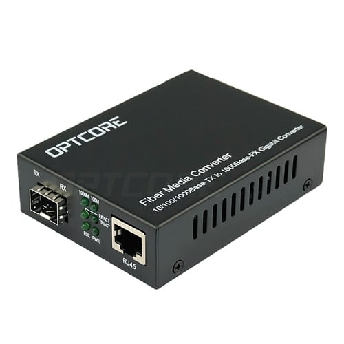
Function of the indicator light of the optical transceiver and method for determining the fault

1. First, do you see if the indicator of the fiber transceiver or optical module and the twisted pair port indicator are on?

  A. If the optical port (FX-LINK/ACT) indicator of the transceiver is not lit, please confirm whether the fiber link is correct cross-link, fiber-optic jack TX-RX; RX-TX.

  B. If the optical port (FXFX-LINK/ACT) indicator of the A transceiver is on and the optical port (FXFX-LINK/ACT) indicator of the B transceiver is not lit, the fault is on the A transceiver side: one possibility is: The A transceiver (TX) optical transmission port is broken because the optical port (RX) of the B transceiver does not receive the optical signal; the other possibility is that the optical link of the A transceiver (TX) optical transmission port has Problem (the cable or fiber jumper may be broken).

  C. The twisted pair (TXFX-LINK/ACT) indicator does not light. Please make sure that the twisted pair cable is faulty or connected incorrectly. Please use the continuity tester (but some transceivers have twisted pair indicators). It must be lit after the fiber link is connected.)

  D. Some transceivers have two RJ45 ports: (To HUB) indicates that the connection line connecting the switches is a straight-through line; (To Node) indicates that the connection line connecting the switches is a cross-line.

  E. Some transceivers have an MPR switch on the side: the connection line connecting the switch is a straight-through mode; the DTE switch: the connection line connecting the switches is a cross-line mode.

  2. Is the optical cable and fiber jumper broken?

  A. The cable on/off detection: use laser flashlight, sunlight, illuminator to illuminate one end of the cable connector or coupler; see if there is visible light on the other end? If there is visible light, it means that the cable is not broken.

  B. Optical fiber connection continuity detection: use laser flashlight, sunlight, etc. to illuminate the fiber jumper; see if there is visible light on the other end? If there is visible light, the fiber jumper is not broken.

  3. Is there a mistake in the half/full duplex mode?

  Some transceivers have FDX switches on the side: full duplex; HDX switches: half duplex.

  4, using optical power meter instrument detection

  The luminous power of a fiber optic transceiver or optical module under normal conditions:

  Multimode 2Km: between -10db and 18db;

  Single mode 20 km: between -8 dB and 15 dB;

  Single mode 60 km: between -5db and 12db;

  If the luminous power of the optical transceiver is between -30db and 45db, then it can be judged that there is a problem with this transceiver.

Posted on Leave a comment

Fiber knowledge commonly used in weak current engineering

Fiber type

Optical cables are classified into indoor optical cables, outdoor optical cables, branch optical cables, and distribution optical cables depending on the application. Optical fibers can be divided into single mode and multimode according to the transmission mode, so monitoring generally uses single-mode fiber.

Single-mode fiber: An optical fiber that transmits only one mode optical signal. Conventionally, G.652, G.653, G.654, and G.655 are classified into transmission classes. Single-mode optical fiber transmits hundreds of megabits of signals up to several tens of kilometers.

Multimode fiber: A fiber that can transmit multiple modes of optical signals. It is G.651 grade. It is divided into OM1, OM2, and OM3 according to the optical mode. The maximum transmission distance of multi-mode fiber transmission is 100 kilometers.

Fiber laying method

Conventional outdoor optical cables are containers with loose tubes as the core, which is the most common fiber core laying method.

Indoor fiber optic cables are often laid tightly.

The core of the large-core optical cable also has a fiber core laminated in a strip form.

Cable structure

1 The most common cable structure is a layer-wound cable. The cable with more than 12 cores is generally of this kind. The cable cavity can accommodate multiple loose tubes, and the loose tube is the basic unit. Each loose tube can accommodate 6- 12-core core; the layer-wound cable is the center reinforcement member, and the loose tube is wrapped around the center reinforcement core. For practical applications, the core needs to be covered with different colors, a total of 12 colors, and the loose-layer cable is loose. The number of tubes is generally also less than 12, so the number of cores of the stranded cable is generally from 12 cores to 144 cores.

2 The structure of the outdoor optical cable below 12 cores is generally the center beam tube type. This type of optical cable has a central loose tube built in, which can contain 1-12 cores, and the outer sheath contains two parallel wires.

3 ribbon cable, also known as skeleton slot structure, is generally used as a cable structure with a large number of cores.

Fiber optic equipment

Optical fiber distribution frame (box): The fiber terminal box is used to protect the fiber and the pigtail. The pigtail is used to connect the fiber transceiver, fiber switch or optical transceiver.

Fiber optic terminal box (connector or splice tray): The fiber optic splice box fuses two fibers together.

Pigtail: One end of the fiber pigtail is fused to the fiber and the other end is connected to a fiber transceiver or fiber switch.

ODF fiber distribution frame and optocoupler: In some large and medium-sized monitoring projects, equipment such as ODF fiber distribution frame and optical coupler may be used. ODF optical distribution frame is mainly used in the equipment room, which can make many optical fibers more regular. Easy to maintain.

Optical fiber transceiver: Also known as the photoelectric converter, the device that converts the optical port and the electrical port is used in pairs. The electrical port is connected to the switch, and the optical port is connected to the fiber pigtail.

Fiber optic module: The main application of the fiber optic module and the fiber switch can directly connect the fiber pigtail to the switch through the fiber module, eliminating the fiber transceiver, but the price of the fiber switch is relatively high.

Disclaimer: All information indicated as other sources is transferred from other platforms, the purpose is to convey more information, does not represent the views and positions of this site. Please contact us if there is any infringement or objection.
 

Posted on Leave a comment

What are the classifications of fiber distribution frames?

The optical fiber distribution frame is connected to the optical fiber connector. In the integrated wiring, the optical fiber distribution frame appears after the optical fiber appears, and the optical fiber generally appears in the vertical subsystem, then the problem comes, what is the optical distribution frame? classification? What are the functions of the fiber distribution frame? How to calculate the fiber distribution frame?


1. What are the classifications of optical distribution frames?

Unit type

A unitized fiber distribution frame is a unit in which multiple units are mounted, each unit is a separate fiber distribution frame. The patch panel not only retains the characteristics of the original small and medium-sized optical fiber distribution frame, but also provides space utilization through the structural deformation of the frame, and is a common structure in the early stage of the large-capacity optical fiber distribution frame. However, due to its inherent limitations in space provision, there is some inconvenience in operation and use.

Drawer type

The drawer type fiber distribution frame also divides a frame into a plurality of units, each unit consisting of one or two drawers. When welding and adjusting the thread, the corresponding drawer is pulled out to operate outside the rack, so that there is a large operation space, so that the units do not affect each other.

The drawer is provided with locking devices in both the pull-out and push-in states to ensure stable and accurate operation and safe and reliable connection of the components in the unit.

Although such a fiber distribution frame ingeniously provides a large space for the operation of the optical cable terminal, as with the unit type, the maximum convenience is not provided in the storage and deployment of the optical connection line. This type of rack is currently the most common form.

Modular

The modular structure divides the fiber distribution frame into a plurality of functional modules, the fusion, wiring, connection line storage and other functional operations of the optical cable are respectively completed in each module, and the modules can be assembled and installed in a common rack as needed. Inside. This structure provides maximum flexibility and better meets the needs of communication networks.

The modular high-capacity optical fiber distribution frame adopts a unique structure such as a panel and a drawer to make the welding and adjusting operation of the optical fiber more convenient. In addition, the vertical wire through and the intermediate distribution frame are used to effectively solve the cloth of the pigtail. Put and store problems. Therefore, it is the most popular type of large-capacity fiber distribution frame, but its cost is relatively high.

Second, what are the functions of the fiber distribution frame?

Optical fiber distribution frame plays an important role in the safe operation and flexible use of optical fiber communication networks, which are embodied in the following four aspects:

After the fiber jumper enters the rack, the fiber distribution frame can fix the fiber jumper to the frame, and mechanically fix the outer sheath and the reinforcing core to protect the fiber jumper from external mechanical damage.

The fiber distribution frame adopts a box structure, which saves space and optimizes cable management.

The high-density pre-terminated system used in fiber distribution frames enhances network performance and makes the network reliable and scalable.

Fiber distribution frames enable easy and fast deployment of high-density interconnects and cross-connects in the data center, simplifying cabling deployments, increasing wiring density, and effectively reducing cabling failures and making cabling flexible.

Third, how to calculate the fiber distribution frame

Take 6-core indoor multimode fiber and 24-port fiber distribution frame as an example:

Assuming there are a central computer room and 5-floor wiring closets, then it is certain that there are 5 fibers.

At this time, the fiber distribution frame is 5 (one per floor wiring) +1 (one in the central room) = 6

Center room fiber distribution frame = 4 (4 core fiber) * 5 (5 fibers) = 20, 20 < 24, so only one is enough, if it is 10 fibers, it is 4 * 10 = 40, 40<48, at this time the center room needs 2 lights.

There is also a situation that is often encountered in actual operation. On the first floor, there is a central computer room and a floor wiring closet. In this case, if everything is in the same cabinet, the fiber can be combined into the same optical distribution. . for example.

6-core indoor multimode fiber and 24-port fiber distribution frame, one central computer room and 5-floor wiring closets

If the central computer room and the floor wiring closet on the 1st floor are on the 1st floor, there are 24 fiber points on the 1st floor (4*5+4), just one 24-port light is enough, so this time We can also solve the problem with 5 light distributions.

Regarding the knowledge about optical fiber distribution frames, today’s Xiaobian will explain to you here first. It is also an extremely important and complicated task in the selection of optical fiber distribution frames. We should fully consider various situations according to specific situations. Factors, based on repeated comparisons, can select a fiber distribution frame that best meets current needs and future development.

(This article is from the Internet, compiled and edited by thousands of hackers. If there is any infringement, please contact to delete.)

This article was first published in the thousand integrated wiring network: http://cabling.qianjia.com/html/2019-04/24_334470.html

Disclaimer: All information indicated as other sources is transferred from other platforms, the purpose is to convey more information, does not represent the position and position of the site and is responsible for its authenticity. If there is any infringement or objection, please contact us to delete.

Posted on Leave a comment

Fiber optic knowledge

Fiber optic knowledge

1 The tensile strength of the fiber is very high, close to the tensile strength of the metal;

2 The ductility of the fiber (1%) is worse than that of the metal (20%);

3 When there are cracks in the fiber, bubbles or debris, under certain tension, it is easy to break;

4 fiber rainwater is easy to break, and the cutting loss is greatly increased;

5 Loss increases with decreasing temperature at low temperatures;

6 Fibers need to be protected from mechanical properties and require waterproof protection to ensure transmission performance.

Wavelength: Communication window of optical fiber communication optical signal, wherein 850, 1310nm is a multi-mode fiber communication window, which is a short-wavelength window; 1310, 1550, 1640nm, etc. is single-mode optical fiber communication with a long-wavelength window.

Simplex: The signal on the communication is only received or not sent, and the one-way communication is understood to be that only one optical fiber is received or only the optical signal is transmitted.

Duplex: Both receiving signals and transmitting signals, which are divided into half-duplex and full-duplex. Half-duplex can be understood as a core optical core. After receiving the signal, the signal can be sent through the same core fiber, but only at this time. Can not send signals cannot be received; and full-duplex is still using a core fiber while receiving signals can continuously send signals, receiving and transmitting two kinds of communication without interference, generally through frequency division multiplexing, time division multiplexing and waves Divided by multiplexing.

Disclaimer: All information indicated as other sources is transferred from other platforms, the purpose is to convey more information, does not represent the views and positions of this site. Please contact us if there is any infringement or objection.

Posted on Leave a comment

What do the six indicators of the fiber transceiver mean?

Our commonly used fiber optic transceivers have 6 indicators, so what does each indicator mean? Is it true that all the indicators are lit to indicate that the fiber transceiver is working properly?

  PWR: Lights up to indicate that the DC5V power supply is working properly.

  FDX: Lights up to indicate that the fiber transmits data in full duplex mode;

  FX 100: Lights up to indicate that the optical fiber transmission rate is 100Mbps;

  TX 100: The light is on, indicating that the twisted pair transmission rate is 100 Mbps, and the light is off, indicating that the twisted pair transmission rate is 10 Mbps;

  FX Link/Act: The long light indicates that the fiber link is connected correctly; the flashing light indicates that data is being transmitted in the fiber;

  TX Link/Act: The long light indicates that the twisted pair link is connected; the light flashes to indicate that there is data in the twisted pair that is transmitting 10/100M.

  If the optical transceiver is working properly, the PWR power indicator must be steady on. The FX-LINK/ACT fiber link indicator and the TX-LINK/ACT network link indicator must be on or blinking. If the LINK/ACT indicator is off. Check whether the link is normal. The FDX working mode indicator, FX-100 fiber rate indicator and TX-100 network rate indicator are not on the fiber transceiver.

Disclaimer: All information indicated as other sources is transferred from other platforms, the purpose is to convey more information, does not represent the views and positions of this site. Please contact us if there is any infringement or objection.
Posted on Leave a comment

Introduction of optical fiber

1 Overview

Fiber and coaxial cables are similar except that there is no mesh shield. The center is the light-transmitting glass core. In a multimode fiber, the core has a diameter of 15 mm to 50 mm, which is roughly equivalent to the thickness of a human hair. The single-mode fiber core has a diameter of 8 mm to 10 mm. The outside of the core is surrounded by a glass envelope having a lower index of refraction than the core to maintain the fiber within the core. Next to it is a thin plastic jacket to protect the envelope. The fiber is usually bundled and protected by an outer casing. The core is usually a double-layer concentric cylinder made of quartz glass with a small cross-sectional area, which is brittle and easily broken so that a protective layer is required. Its structure is shown in Figure 1.

The fiber on the land is usually buried 1 meter underground, sometimes damaged by underground small animals. Near the coast, the transoceanic fiber casing is buried in the ditch. In deep water, they are at the bottom and are most likely to be bitten by fish or crashed by fishing boats.

2, classification

Optical fiber is mainly divided into the following two categories:

1) Transmission point modulus class

Transmission point analog-to-digital single mode Fiber (Single Mode Fiber) and multimode fiber (Multi-Mode Fiber). The single-mode fiber has a small core diameter and can only be transmitted in a single mode at a given operating wavelength, with transmission bandwidth and large transmission capacity. Multimode fiber is an optical fiber that can transmit simultaneously in multiple modes at a given operating wavelength. Multimode fiber has poorer transmission performance than single mode fiber.

2) Refractive index distribution class

Refractive index distribution fibers can be classified into hopping fibers and grading fibers. The refractive index of the hopping fiber core and the refractive index of the protective layer are both constant. At the interface between the core and the protective layer, the refractive index changes stepwise. The refractive index of the graded fiber core decreases with a certain radius as the radius increases and decreases to the refractive index of the protective layer at the interface between the core and the protective layer. The change in the refractive index of the core approximates the parabola. The refractive index distribution type fiber beam transmission is shown in Fig. 2.

3, the connection method

There are three ways to connect the fiber. First, they can be plugged into the connector and plugged into a fiber optic socket. The connector loses 10% to 20% of the light, but it makes it easy to reconfigure the system.

Second, it can be joined mechanically. The method is to place one end of two carefully cut fibers in a sleeve and then clamp them. The fiber can be adjusted through the junction to maximize the signal. The mechanical combination requires trained personnel to take about 5 minutes to complete, and the loss of light is about 10%.

Third, the two fibers can be fused together to form a solid connection. The fiber formed by the fusion method is almost the same as the single fiber, but it also has a little attenuation. For all three connection methods, there is a reflection at the junction and the reflected energy interacts with the signal.

4, send and receive

There are two types of light sources that can be used as signal sources: light-emitting diodes (LEDs) and semiconductor lasers (LDs). They have different characteristics, as shown in the following table.

projectledSemiconductor laser
Data ratelowhigh
modeMultimodeMultimode or single mode
distanceshortlong
Life cyclelongshort
Temperature sensitivitySmallerMore sensitive
CostLow costexpensive

The receiving end of the fiber is made up of a photodiode that gives a point pulse when it encounters light. The response time of a photodiode is typically 1 ns, which is why the data transfer rate is limited to 1 Gb/s. Thermal noise is also a problem, so the light pulse must have enough energy to be detected. If the pulse energy is strong enough, the error rate can be reduced to a very low level.

5, the interface

There are two types of interfaces currently in use. The passive interface is formed by two streets fused to the main fiber. One end of the connector has a light emitting diode or laser diode (for transmission). At the other end, there is a photodiode (for receiving). The joint itself is completely passive and therefore very reliable.

Another type of interface is called an active repeater. The input light is converted into an electrical signal in the repeater, and if the signal has been attenuated, it is re-amplified to the maximum intensity, then converted to light and sent out. Connected to the computer is a common copper wire that enters the signal regenerator. There is now a pure optical repeater that does not require optoelectronic conversion and can, therefore, operate at very high bandwidth.

Disclaimer: All information indicated as other sources is transferred from other platforms, the purpose is to convey more information, does not represent the views and positions of this site. Please contact us if there is any infringement or objection.
Posted on Leave a comment

Introduction of leather cable and its product features and structure

Brief introduction of leather cable

The leather cable is commonly known as an indoor hanging wiring cable. In the case that the domestic fiber access market shows a good momentum of development, fiber access has become a hot spot in the field of optical communications. In the fiber access engineering, the indoor wiring close to the user is the most complicated link. The bending performance and tensile performance of the conventional indoor optical cable cannot meet the requirements of FTTH (Fiber to the Home) indoor wiring.
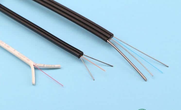
The access network uses a dish-shaped cable (for indoor wiring) with the optical communication unit (fiber) in the center, two parallel non-metallic reinforcements ( FRP ) or metal reinforcement members placed on both sides , and finally, black or colored poly It is made of vinyl chloride ( PVC ) or low-smoke halogen-free material (LSZH, low-smoke, halogen-free, flame retardant).

Feature

Special bend-resistant fiber to provide greater bandwidth and enhance network transmission performance;

Two parallel FRP or metal reinforcements provide good compression resistance and protect the fiber;

The cable has the advantages of simple structure, lightweight and strong practicability;

Unique groove design, easy to peel, easy to connect, simplify installation and maintenance;

Low-smoke, halogen-free flame-retardant polyethylene sheath or flame-retardant PVC sheath, environmentally friendly.

It can be matched with a variety of field connectors and can be field-proven.

The leather fiber optic cable is characterized by its softness and lightness; it is widely used in the access network; the name of the leather cable: the access network is

introduced into the cable by a butterfly; because of its shape, it is called a butterfly cable. 8-word cable.

product structure

The ordinary leather cable is a standard 8-shaped structure; two parallel reinforcing cores with fiber in the middle; self-supporting leather cable adds a thick steel wire to the structure of ordinary leather cable; overall self-supporting leather The line cable is just one more wire, and the others have not changed.
This type of fiber optic cable has a different structure for each manufacturer. However, it is generally not a metal reinforcing core, and a butterfly-shaped cable is taken as an example. The cross-section is like a butterfly, so it is called. Both sides are reinforcing members in the leather line and optical fibers in the middle.
1. The butterfly-shaped optical cable is divided into indoor and outdoor (inside) and outside, the price difference between the two is large, and the outdoor price is about twice the price of the indoor type. In general, the price factor should be considered when making a specific design. Under normal circumstances, The outdoor fiber optic cable (GYTA-G 652D) is still used outdoors, and the indoor butterfly cable is used for the transition between the two through the fiber box or the joint box.
2. The butterfly cable has a small radius of curvature, lightweight, relatively good bending resistance, easy to fix, and easy termination in the 86 terminal box.
3. Butterfly-shaped fiber-optic cables are available in non-metallic reinforcing members and metal-reinforced members. In view of lightning protection and strong electrical interference, indoor non-metallic reinforcing members butterfly cables should be used.
4, indoor butterfly cable has 1 core, 2 core, 3 core, 4 core, and other specifications, residential users should choose single-core cable for butterfly-shaped household cable; business users can access butterfly cable for 2–4 Core cable design.
The connection has a cold connection and welding.
The cold connection is to install the fiber end face by connecting the fiber end face and connect it with the flange head.

Applications

For indoor wiring, the end user directly uses the cable;
Used for building incoming optical cables;
User wiring for FTTH.

Executive standard

YD/T1997-2009 The access network uses a dish to introduce fiber optic cable.

Structural parameters

Reinforcement type Cable size (mm) Allowable tensile force (N)
long/short term
Allowable crushing force (N/100mm)
long/short term
Non-metallic reinforcement 3.0×2.0 40/80 500/1000
Metal reinforcement 3.0×2.0 100/200 1000/2000
coding product name Description
NFC8101F Single core single mode indoor leather cable OS1, non-metallic reinforcement, flame retardant PVC jacket
NFC8102F Double core single mode indoor leather cable OS1, non-metallic reinforcement, flame retardant PVC jacket
NFC8102FL Double core single mode indoor leather cable OS1, non-metallic reinforcement, low smoke zero halogen LSZH jacket
NFC8102 Double core single mode indoor leather cable OS1, metal reinforcement, flame retardant PVC jacket
NFC8102L Double core single mode indoor leather cable OS1, metal reinforcement, low smoke zero halogen LSZH jacket

Disclaimer: All information indicated as other sources is transferred from other platforms, the purpose is to convey more information, does not represent the views and positions of this site. Please contact us if there is any infringement or objection.

Posted on Leave a comment

What is the difference between a transmission optical port and an electrical port?

Optical port
The optical port is an abbreviation of the optical fiber interface.
Also known as G port (meaning G fiber port)
Optical port: A fiber-optic bandwidth interface used in large equipment such as equipment rooms and cabinets.

Fibers can be used for audio (sound card with light output), network (fiber as a transmission medium), disk (fiber instead of cable for data transmission), and more.
Optical fibers can be divided into single-mode fibers and multimode fibers. The differences are as follows:
Single mode fiber and multimode fiber can be easily discriminated from the size of the core. The core of a single-mode fiber is small, about 4 to 10 um, and only transmits the main mode. This completely avoids modal dispersion and makes the transmission band wide.

The transmission capacity is large. This fiber is suitable for high-capacity, long-distance fiber-optic communications. It is an inevitable trend in the future development of optical fiber communication and lightwave technology.
Multimode fibers are further classified into multimode abrupt fibers and multimode graded fibers. The former has a larger core diameter and more transmission modes, so the bandwidth is narrower and the transmission capacity is smaller;
In the latter core, the refractive index decreases as the radius increases, and a relatively small modal dispersion can be obtained, so that the frequency band is wider and the transmission capacity is larger. Currently, the latter is generally applied.
Since the transmission speeds of different modes of light in a multimode fiber are different, the transmission distance of the multimode fiber is short. Single-mode fiber can be used in non-relay optical communication.

In the theory of optical fiber communication, the optical fiber has single mode and multimode, and the difference lies in:
1. Single-mode fiber has a small core diameter (about 10m), allowing only one mode of transmission, low dispersion, and working at long wavelengths (1310nm and 1550nm), which is relatively difficult to couple with optical devices.
2. The multimode fiber has a large core diameter (62.5m or 50m), allowing transmission in hundreds of modes, large dispersion, and operating at 850nm or 1310nm. Coupling with optical devices is relatively easy.
For the optical module, strictly speaking, there is no single mode or multiple modes. The so-called single-mode, multi-mode module refers to the optical device used by the optical module to match the fiber to obtain the best transmission characteristics.

Generally, there are the following differences:
1. Single-mode modules generally use LD or narrow-spectrum LEDs as the light source. The size of the coupling components is good with single-mode fiber. When transmitting with single-mode fiber, it can transmit longer distances and the price is higher.
2. Multi-mode modules generally use lower-priced LEDs as the light source. The size of the coupling components is well matched with multimode fibers, and the price is relatively cheap.

The electrical port is relative to the optical port and refers to the physical characteristics of the fire extinguisher. It mainly refers to the copper cable and is the processed electrical signal. Currently, the common network interfaces include 100M electrical ports and Gigabit electrical ports.

Simply put, the electrical port is an ordinary network cable interface, the general speed is 10M or 100M, and some support 1000M. The maximum distance of the electrical port is 100 meters.

Disclaimer: All information indicated as other sources is transferred from other platforms, the purpose is to convey more information, does not represent the views and positions of this site. Please contact us if there is any infringement or objection.
Posted on Leave a comment

How to install fiber optic cable

The way of entering home


User room wiring

In the FTTH project, the user’s indoor wiring is the most complicated part, and many factors are considered. It is necessary to ensure the safety of the line, but also to take

into account the indoor beauty, but also to facilitate the construction. The traditional single-core indoor optical cable cannot meet the requirements of the current FTTH

engineering indoor wiring. As a substitute for traditional indoor optical cable, Weipuxin leather cable can adapt to most indoor wiring conditions, such as turning at a

bending radius of 20mm, which can bear the side pressure of people stepping on the cable, and the drag of engineering construction. pull. At the same time, with a variety of

field connectors, real-time end-to-end and docking can be achieved in the shortest time. Therefore, Weipuxin leather cable is the best choice for FTTH indoor wiring.


Vertical horizontal wiring in the building


Like the user’s indoor wiring, the Weipuxin cable is also suitable for vertical horizontal wiring in the building. Horizontal cabling is not very demanding on fiber optic cable,

but vertical cabling must require fiber optic cable to have a certain tensile strength. The lipoxin leather cable can withstand a short-term 200 Newton and long-term 100Newton pulls, so it can guarantee the safety and stability of the vertical wiring of the cable optical cable within a certain height range.


Self-supporting overhead wiring


The self-supporting “8” word wiring cable has a tensile strength and can withstand a span of 50 meters due to its metal suspension unit. The optical cable is laid out in an

overhead manner. The metal suspension unit is cut off before being placed in the house and is fixed on a special fixture. The remaining optical cable is stripped of the metal

suspension wire and then introduced into the room by a leather cable.


Pipeline wiring

Because the pipeline mapping cable is harder than the sheath cable, the tensile strength is higher, and the cable contains water blocking material, which can reduce outdoor rain erosion, so it is suitable for long-distance outdoor pipeline laying. The Vision Information Pipeline Mapping Cable uses an all-metal structure to avoid the introduction of lightning into the room. After the optical cable enters the household, the outer sheath, the water blocking material and the reinforcing member are stripped, and the indoor heating cable is directly used for the indoor wiring, which inherits all the advantages of the indoor wiring of the sheath optical cable, and reduces the connection of the outdoor-indoor optical cable.


Disclaimer: All information indicated as other sources is transferred from other platforms, the purpose is to convey more information, does not represent the views and positions of this site. Please contact us if there is any infringement or objection.