Posted on Leave a comment

Fiber Optic Communications Professional Overview

Optical fiber communications have emerged as one of the main pillars of modern communications and have played a pivotal role in modern telecommunications networks. As an emerging technology, optical fiber communication has developed rapidly in recent years and is widely used in the history of communication. It is also an important symbol of the world’s new technological revolution and the main transmission tool for various information in the future information society.


Professional Overview

The fiber optical is the abbreviation of the optical fiber. Optical fiber communication is a communication method in which light waves are used as information carriers and optical fibers are used as transmission media. In principle, the basic material elements that makeup fiber optic communication are fiber optics, light sources, and photodetectors. In addition to classification according to the manufacturing process, material composition, and optical characteristics, optical fibers are often classified according to their applications and can be classified into communication optical fibers and sensing optical fibers. The transmission medium fiber is divided into two types: general purpose and special purpose, and the function device fiber refers to an optical fiber for performing functions of amplification, shaping, frequency division, frequency multiplication, modulation, and optical oscillation of light waves, and is often used for a certain functional device. The form appears.


Optical fiber communication is a communication method in which optical waves are used as carriers and optical fibers are used as transmission media to transmit information from one place to another. This is called “wired” optical communication. Today, the optical fiber has become the main transmission method in the world communication because of its transmission bandwidth, high anti-interference and low signal attenuation, which is far superior to cable and microwave communication.


In 1966, British Chinese sorghum (Charles Kao) published a paper on the use of quartz to make glass filaments (fibers) with a loss of up to 20dB/km, enabling high-capacity fiber-optic communication. At that time, only a few people in the world believed, such as the British Standard Telecommunications Laboratory (STL), the United StatesCorning Glass Company, Bell Labs and other leaders.


In 2009, Gao Song won the Nobel Prize for inventing fiber. In 1970, Corning developed a quartz fiber with a loss of 20dB/km and a length of about 30 m, which was said to cost $30 million. In 1976, Bell Labs established an experimental circuit in Atlanta, Washington, with a transmission rate of only 45 Mb/s, which can only transmit hundreds of telephones, while a medium-coaxial cable can transmit 1800 telephones. Because when it is fashionable to use a laser for communication but to use a light-emitting diode (LED) as a light source for optical fiber communication, the rate is very low.


Around 1984, the semiconductor laser for communication was successfully developed. The speed of optical fiber communication reached 144 Mb/s, and 1920 telephones could be transmitted. In 1992, a fiber-transmission rate reached 2.5Gb/s, which is equivalent to more than 30,000 telephones.


In 1996, lasers of various wavelengths were successfully developed to realize multi-wavelength multi-channel optical fiber communication, so-called “wavelength division multiplexing” (WDM) technology, that is, transmitting optical signals of multiple different wavelengths in one optical fiber… Thus, the transmission capacity of optical fiber communication is doubled.


In 2000, with WDM technology, a fiber-optic fiber-transmission rate reached 640 Gb/s. Some people invented the fiber in 1976, and there was a big doubt about winning the Nobel Prize in 2010. In fact, it can be seen from the history of the above optical fiber that despite the large capacity of the optical fiber, the high-speed laser and microelectronics cannot function as the ultra-large capacity of the optical fiber. The speed of electronic devices has reached the gigabit/second level, and the emergence of high-speed lasers of various wavelengths has enabled the transmission of optical fibers to the order of terabits/second (1Tb/s = 1000 Gb/s). Triggered a revolution in communication technology!”


Disclaimer: All information indicated as other sources is transferred from other platforms, the purpose is to convey more information, does not represent the views and position of this site. Please contact us if there is any infringement or objection.

Posted on Leave a comment

Fiber optic communication applications and work processes

Work Process

Send: The CPU serializes the parallel data through a dedicated IC chip and inserts the corresponding bit code (start, stop, check digit, etc.) according to the communication format and the signal is sent to the fiber connector by the output terminal TXD. Then, the light source in the optical fiber connector performs the electro-optical conversion and the converted optical signal transmits an optical signal to the optical fiber through the optical fiber plug, and the optical signal propagates forward in the optical fiber.

Receiving: the optical signal from the optical fiber is sent to the receiver of the fixed plug through the moving plug of the optical fiber connector, and the receiver optically-electrically restores the received optical signal, thereby obtaining a corresponding electrical signal, and the electrical signal is sent to The RDX input terminal of the dedicated IC chip is converted to parallel data by the dedicated IC chip and then transmitted to the CPU.

Application field

The application fields of optical fiber communication are very wide, mainly used for local telephone trunk lines. The advantages of optical fiber communication can be fully utilized here, and the cable is gradually replaced, which is widely used. Also used for long-distance trunk communication in the past mainly relying on cable, microwave, satellite communication, and now gradually use fiber-optic communication and form a globally advantageous bit transmission method; for global communication networks, public telecommunications networks of various countries (such as China’s national one) Level trunk line, provincial secondary line and sub-sector branch line).

It is also used for high-quality color TV transmission, industrial production site monitoring and dispatching, traffic monitoring, and control command, town cable TV network, shared antenna(CATV) system, Used in fiber optic LANs and others such as in aircraft, in spacecraft, in ships, undermines, in the power sector, in military applications, and in corrosive and radiative applications.

The optical fiber transmission system mainly consists of an optical transmitter, an optical receiver, an optical cable transmission line, an optical repeater, and various passive optical components. To communicate, the baseband signal must be further electrical terminals of the unit after the signal processing to the optical fiber transmission system to complete the communication process.

It is suitable for use in fiber optic analog communication systems, but also for fiber optic digital communication systems and data communication systems. In the optical fiber an analog communication system, the electrical signal processing refers to the processing of amplifying and pre-modulating the baseband signal, and the electrical signal processing is the inverse process of the originating processing, that is, demodulation, amplification, and the like.

In the optical fiber digital communication system, electrical signal processing refers to amplification, sampling, and quantization of the baseband signal, that is, pulse code modulation (PCM) and line code type encoding processing, and the electrical signal inverse processing is also the inverse process of the originating end. For data fiber communication, electrical signal processing mainly involves amplifying the signal. Unlike digital communication systems, it does not require pattern conversion.

Posted on Leave a comment

Fiber definition and technology

optical fiber

The optical fiber is the transmission channel of optical signals and is the key material for optical fiber communication.
The optical fiber consists of a core, a cladding, a coating layer, and a jacket, and is an asymmetrical cylinder of a multilayer dielectric structure. The main body of the core is
silica, which is doped with trace amounts of other materials to increase the refractive index of the material. The outer core has a cladding layer, and the cladding has a
different refractive index from the core and the core has a higher refractive index to ensure that the optical signal is mainly transmitted in the core. Outside the cladding is a
layer of paint that is used primarily to increase the mechanical strength of the fiber so that the fiber is not damaged by external damage. The outermost layer of the fiber is a
jacket and is also protective.
The two main features of an optical fiber are loss and dispersion. The loss is the attenuation or loss of the optical signal per unit length, expressed in dB/km. This parameter is
related to the transmission distance of the optical signal. The larger the loss, the shorter the transmission distance. Multi-microcomputer elevator control systems generally
have a short transmission distance, so in order to reduce costs, plastic optical fibers are mostly used. The dispersion of the fiber is mainly related to pulse broadening. In the
Mitsubishi elevator control system, optical fiber communication is mainly used for data transmission between group control and single ladder and data transmission between
two parallel single ladders. The fiber optic device used in the Mitsubishi elevator is mainly composed of a light source, an optical receiver, and an optical fiber, wherein the
light source and the optical receiver are packaged in a fixed plug of the optical fiber connector, and the optical fiber is connected to the movable plug.

Optical wavelength division multiplexing

WDM (Wavelength Division Multiplexing) technology refers to the use of multiple lasers to simultaneously transmit multiple wavelengths of light on the same fiber. It can

greatly increase the transmission capacity of the fiber transmission system. Currently, 1.6 Tbit/s WDM systems have been commercialized on a large scale. In order to further

increase the capacity of optical fiber transmission, the DWDM (Dense Wavelength Division Multiplexing) foundation became the main research object in the world after

1995. Lucent Bell Labs believes that the commercial DWDM system capacity can reach 100 Tbit/s. At present, DWDM based on 10 Gbit/s has gradually become the

mainstream of core networks among many operators in China. In addition to the increasing number of wavelengths and transmission capacity of the DWDM system, the

optical transmission distance has also increased from 600 km to over 2000 km. In addition, Coarse Wavelength Division Multiplexing (CWDM) has also emerged in the

expansion of metro optical transport networks, with advantages such as large capacity, short-distance transmission and low cost. The researchers also found that wavelength

division multiplexing of multiple optical time division multiplexed OTDM signals can greatly increase transmission capacity. As long as the appropriate combination can

achieve Tbit / s transmission, it is also the future development direction of optical fiber communication. Most of the transmission experiments in the laboratory over 3 Tbit/s

are implemented in this way.

Optical soliton communication technology

Light is a special ultra-short optical pulse on the order of ps. After long-distance transmission through the fiber, the waveform and speed remain unchanged. Optical soliton

communication uses optical soliton as a carrier to realize long-distance undistorted communication. In the case of zero error, information transmission can reach thousands
of miles. Numerous experiments have shown that it can be used for submarine cable communication, etc., and is suitable for combination with WDM systems to form ultra-
high-speed and large-capacity optical communication. When the single-channel rate reaches 40 Gbit/s or more, the advantages of optical soliton communication are fully

realized.

Fiber access technology

Fiber access using PON technology can be combined with a variety of technologies, such as ATMSDH and Ethernet, to generate APON, GPON, and EPON, respectively. In
contrast, EPON inherits the advantages of Ethernet and the cost is relatively low. After combining with fiber technology, EPON is not limited to local area networks, but also
extends to metropolitan area networks and even wide area networks. Now, fiber-to-the-home adopts EPON technology; GPON has the most advantages in circuit-switched
service support, and can fully utilize existing SDH technology, but the technology is more complicated and the cost is higher; APON will be used to implement FTTH solution.
Disclaimer: All information indicated as other sources is transferred from other platforms, the purpose is to convey more information, does not represent the views and
positions of this site. Please contact us if there is any infringement or objection.

Posted on Leave a comment

Development of optical switching

Development of optical switching
In fact, it can be expressed as communication + exchange.
Optical fiber only solves the transmission problem and needs to solve the problem of optical exchange. In the past, communication networks were made up of metal cables,
which transmitted electronic signals, and exchanges were made using electronic switches. In addition to a short segment of the user’s end, the communication network is an
optical fiber that transmits optical signals. A reasonable approach should be to use optical switching. However, since the optical switching device is not mature, only the
“optical-electric-optical” method can be used to solve the exchange of the optical network, that is, the optical signal is converted into an electrical signal, and after being
exchanged by the electronic, the optical signal is returned. Obviously, it is an unreasonable way, and the effect is not high and uneconomical. Large-capacity optical switches
are being developed to implement optical switching networks, especially the so-called ASON-auto-switched optical networks.

Usually, the information transmitted in the optical network is generally Gbps, and the electronic switch is not competent. It is generally necessary to implement an electronic

exchange in a low-order group. Optical switching enables high-speed XGbDs to be exchanged. Of course, it is not to say that everything must be exchanged by light, especially

the exchange of low-speed, small-particle signals. The mature electronic exchange should be used. It is not necessary to adopt immaturely

Large-capacity optical switching. Currently, in data networks, signals appear in the form of “packets”, using so-called “packet switching.” The particles of the bag are relatively
small and can be exchanged by electrons. However, after a large number of packets in the same direction are aggregated, when the number is large, a large-capacity optical
the switch should be used.
Less channel and large capacity optical switching have been practical. Such as for protection, downlink, and small-scale path scheduling. It is generally realized by the
mechanical optical switch and thermo-optical switch. Due to the limitations of the size, power consumption, and integration of these optical switches, the number of channels
is generally 8-16.
Electronic exchange generally has “space division” and “time division” methods. There are “space division”, “time division” and ” wavelength exchange ” in optical
switching. Optical fiber communication rarely uses optical time division switching.
Optical space switching: Generally, an optical switch can be used to transfer an optical signal from one optical fiber to another optical fiber. The optical switches of air
separation has mechanical, semiconductor and thermo-optic switches. Using integrated technology, the MEM micromotor optical switch was developed with a volume as
small as me. The 1296×1296 MEM optical switch (Lucent) has been developed and is experimental in nature.
Optical wavelength switching: assigns a specific wavelength to each switching object. Thus, a certain specific wavelength can be transmitted to communicate with a specific
object. The key to achieving optical wavelength switching is the development of practical variable wavelength light sources, optical filters, and integrated low power, reliable
optical switch arrays. A cross-connection test system (Corning) combining the space and wavelength of a 640×640 semiconductor optical switch + AWG has been
developed. The use of optical space division and optical wavelength division can constitute a very flexible optical switching network. Japan’s NTT conducted field trials using
wavelength routing exchange in Chitose City, with a radius of 5 kilometers and a total of 43 terminal sections (using 5 nodes) at a rate of 2.5 Gbps.
The automatically switched optical network, called ASON, is the direction of further development.
Disclaimer: All information indicated as other sources is transferred from other platforms, the purpose is to convey more information, does not represent the views and
positions of this site. Please contact us if there is any infringement or objection.

Posted on Leave a comment

Development of optical fiber communication

Development of

Optical fiber communication is the main transmission means of modern communication networks. Its development history is only one or two decades. It has experienced
three generations: short-wavelength multimode fiber, long-wavelength multimode fiber, and long-wavelength single-mode fiber. The use of optical fiber communication is a
major change in the history of communications. More than 20 countries such as the United States, Japan, Britain, and France have announced that they will no longer build
cable communication lines, and are committed to the development of fiber-optic communications. China’s optical fiber communication has entered a practical stage.
The birth and development of optical fiber communications are telecommunications an important revolution in the history of satellite communications, mobile
communications tied to the technology of the 1990s. After entering the 21st century, due to the rapid development of Internet services and the growth of audio, video, data,
and multimedia applications, there is a more pressing need for high-capacity (ultra-high-speed and ultra-long-haul) optical wave transmission systems and networks.
Optical fiber communication is a new communication technology that uses optical waves as a carrier to transmit information and optical fiber as a transmission medium to
achieve information transmission.
The development process of communication is to continuously increase the carrier frequency to expand the communication capacity. The optical frequency as the carrier
the frequency has reached the upper limit of the communication carrier. Because light is an electromagnetic wave with extremely high frequency, the communication capacity
is very large with light as a carrier. It is a thousand times of communication methods in the past, and it has great attraction. Optical communication is the goal that people
have long pursued, and it is also the inevitable direction of communication development.
Compared with the previous electrical communication, the main difference of optical fiber communication is that it has many advantages: it has a wide transmission
bandwidth and large communication capacity; low transmission loss and long relay distance; fine wire diameter and lightweight; the raw material is quartz, saving metal
materials. Conducive to the rational use of resources; strong insulation and anti-electromagnetic interference; also has the advantages of strong anti-corrosion ability, strong
radiation resistance, good routable, no electric spark, small leakage, strong confidentiality, etc., can be used in a special environment or military Used on.
Disclaimer: All information indicated as other sources is transferred from other platforms, the purpose is to convey more information, does not represent the views and
positions of this site. Please contact us if there is any infringement or objection.

Posted on Leave a comment

Detailed introduction of fiber optic transceiver products

One. Overview
* Optical transceiver is an optical signal converter used to convert electrical signals from computer networks into optical signals.
* Our 10/100M adaptive optical transceiver is fully compliant with IEEE802.3 10BaseT, IEEE802.3u 10BaseTX. 10Base-FX standard;
* 10/100M adaptive optical transceiver is divided into multimode fiber transceiver and single mode fiber transceiver;
* Optical transceiver has one RJ45 interface and one SC/ST interface. Used to connect twisted pair and fiber respectively;
* The fiber transceiver has 6 LED indicators: POWER, FX100, TX100, FXlink/Act, TXlink/Act, Fdx.
10/100Base-TX to 100Base-FX SFP Fiber Media Converter
two. Installation and Initialization

Follow these steps to install a 10/100M adaptive fiber transceiver:
1. Connect the fiber jumper or tail cable from the fiber optic terminal box to the fiber transceiver. Please note that the sender (TX) of the other device should be connected to the receiver (RX) of the transceiver, and the receiver (RX) of the other device should be connected to the transmitter (TX) of the transceiver.
2. The UTP jumper connector RJ45 interface from the network device to the fiber optic transceiver, straight or crossing lines selected in accordance with the fiber optic transceiver of claim docking device, generally exchange
required line cross-connect machines, and other network devices address, A straight-through cable is required to connect to single-address network devices such as servers and workstations.
3. Connect the DC plug of the power adapter to the DC socket of the fiber transceiver, and then plug the AC plug of the power adapter into the AC socket. At this time, the POWER indicator of the light transceiver is on, and the other indicators flash in sequence according to the self-test sequence. After the self-test is completed, the working state of the transceiver will be determined according to the state of the network device that is detected by the fiber transceiver, and the indicator light will display the working state of the transceiver at this time.

Three. LED indicator
The fiber optic transceiver has six LED indicators that show the operating status of the transceiver. Based on the LED indicators, it can be determined whether the transceiver is working properly and may have problems, which can help identify the fault. Their functions are as follows:
PWR: Lights up to indicate that the DC5V power supply is working properly.
FX 100: Lights up to indicate that the fiber transmission rate is 100Mbps.
FX Link/Act: The long light indicates that the fiber link is connected correctly, and the light flashes to indicate that there is data in the fiber. Transmission
FDX: Lights up to indicate that the fiber transmits data in full-duplex mode.
TX 100: Lights up to indicate that the twisted pair transmission rate is 100 Mbps; when the light is off, the twisted pair transmission rate is 10 Mbps.
TX Link/Act: The light is long and the twisted pair is connected. The road is connected correctly; the light flashes to indicate that there is data in the twisted pair

.

model
Fiber optic interfaceSC/STSCSCSC
Fiber typeMultimodeMultimodeMultimodeMultimode
Center wavelength850/1310nm1310nm1310nm1310nm
Transmission distance2 km25 km40 km60 km
Minimum transmit power-19.0dBm-15dBm-9.0dBm-4.0dBm
Maximum transmit power-12.0dBm-9.0dBm-5.0dBm0dBm
Receiving sensitivity<-30dBm<-32dBm<-35dBm<-38dBm
Allow link loss11.0dBm17.0dBm26.0dBm34.0dBm

V. Technical parameter
standard: IEEE802.3 10BaseT, IEEE802.3u 10Base-TX, 10Base-FX standard
interface: twisted pair: RJ45
fiber: SC or ST
LED: PWR, FX 100, FX Link/Act, FDX, TX 100 , TX Link/Act
transmission rate: twisted pair: 10Mbps, 100Mbps
fiber: 100mbps
duplex mode: full or half duplex
twisted pair: Category 5 5E
fiber: multimode 50/125, 62.5/125μm
single mode :8.3/125,9/125,10/125μm
Power supply: AC 220V (175-250V), 50Hz
DC: 5V, 1A
Ambient temperature: 0~50 C
Storage temperature: -20~70 C
Humidity: 5%~90%
volume : 26 × 70 × 95mm (height × width × length)VI. Packing list
fiber optic transceiver
AC22V / DC5V power adapter 1 only
instructions for use 1
note: 1. Fiber interface is always set to 100M full duplex mode
2. Double When the twisted-line interface is initialized, its own state is set according to the state of the detected docking device. If the other party’s state is not detected, the state is undefined.
3. Lightning induction damage chip is not covered by the free warranty

Disclaimer: All information indicated as other sources is transferred from other platforms, the purpose is to convey more information, does not represent the views and positions of this site. Please contact us if there is any infringement or objection.

Posted on Leave a comment

Common single mode fiber

Single Mode Fiber: The center core is very thin (the core diameter is generally 9 or 10 μm), and the single-clad outer diameter is 125 μm, which is expressed as 9/125

μm. Only one mode can be transmitted (degenerate two polarization states). Therefore, the inter-mode dispersion is small, suitable for remote communication, but there are

also material dispersion and waveguide dispersion, so that single-mode fiber has high requirements on the spectral width and stability of the light source, that is, the spectral

width is narrow and stable. It’s better.

It was later found that at a wavelength of 1310 nm, the total dispersion of the single mode fiber is zero. From the loss characteristics of the fiber, 1310nm is just a low loss

window of the fiber. Thus, the 1310 nm wavelength region has become an ideal working window for fiber-optic communication and is also the main working band of practical

fiber-optic communication systems. The main parameters of the 1310nm conventional single-mode fiber are determined by the International Telecommunication Union ITU-

T in the G652 recommendation, so this fiber is also called G652 fiber. The vast majority of fiber optic cables that have been laid in China are such fibers. With the successful

advancement of the fiber optic cable industry and semiconductor laser technology, the operating wavelength of the fiber line can be transferred to a lower loss (0.22 dB/km)

1550 nm fiber window.

G.653 single mode fiber

A single-mode fiber that meets ITU-TG653 requirements, often referred to as Dispersion Shifted Fiber, has a zero-dispersion wavelength shifted to a very low loss of 1550

nm. However, the existence of DSF is seriously insufficient. There are harmful nonlinear effects such as four-wave mixing in the low dispersion region around 1550 nm, which

hinders the application of the fiber amplifier in the 1550 nm window.

Four-Wave Mixing (FWM), also known as four-phonon mixing, is an inter-wave coupling effect produced by the real part of the third-order polarization of a fiber medium. It

is due to the interaction of two or three light waves of different wavelengths. This results in the generation of so-called mixing products at other wavelengths or new light

waves in the sidebands. This interaction may occur between signals in a multi-channel system and can produce multiple parametric effects such as triple frequency, sum

frequency, and difference frequency.

The reason why the four-wave mixing occurs is that the light at one of the incident lights changes the refractive index of the optical fiber, and the phase of the optical wave

changes at different frequencies, thereby generating a new wavelength of light.

In a DWDM system, four-wave mixing becomes a major factor in nonlinear crosstalk when the channel spacing and fiber dispersion are sufficiently small and phase matching

is satisfied. When the channel spacing reaches below 10 GHz, the impact of the FWM on the system will be most severe.

Addax security engineers believe that the impact of four-wave mixing on the DWDM system is mainly manifested in (1) generating new wavelengths, causing loss of optical

energy of the original signal, affecting the signal-to-noise ratio of the system; (2) If the new wavelength produced is the same as or overlaps with the original wavelength,

serious crosstalk is generated. The generation of four-wave mixing requires the phase matching of each signal light. When each signal light is transmitted near the zero

dispersion of the optical fiber, the influence of material dispersion on the phase mismatch is small, so it is easy to satisfy the phase matching condition and easily generate

four waves. Mixing effect.

The channel spacing of current DWDM systems is generally 100 GHz, and zero-dispersion causes four-wave mixing to become the main reason. Therefore, when G.653 fiber

transmission DWDM system is used, it is easy to generate a four-wave mixing effect, and G.652 or G. At 655 fiber, it is not easy to produce a four-wave mixing

effect. However, G.652 fiber has a certain dispersion in the 1550nm window storage. When transmitting the 10G signal, the dispersion compensation should be added. The

dispersion of G.655 fiber in the 1550nm window is small, which is suitable for transmission of a 10G DWDM system…

G.655 single mode fiber

Single mode fiber that meets ITU-TG 655 requirements, often referred to as a non-zero dispersion shifted fiber or NZDSF (=NonZero Dispersion Shifted Fiber). It belongs to

the dispersion-shifted fiber, but the dispersion is not zero at 1550 nm (the dispersion value corresponding to the range of 1530-1565 nm according to ITU-TG655 is 0.1-6.0

ps/nm.km), which is used to balance the four-wave mixing. Linear effect.

Disclaimer: All information indicated as other sources is transferred from other platforms, the purpose is to convey more information, does not represent the views and

positions of this site. Please contact us if there is any infringement or objection.

Posted on Leave a comment

Characteristics affecting optical transmission performance

1. Propagation of light in optical fibers

For step-index fibers, due to the obvious boundary between the core and cladding refractive index distributions, the light waves from a total reflection at the interface

between the core and the cladding interface, and form a zigzag transmission path, guiding the fiber core to propagate forward…

For the graded-index fiber, since the refractive index is continuously changed at the interface, the refractive index at the center of the shaft is the largest, the refractive index

decreases along the radius of the core in a parabolic law, and the refractive index at the edge of the core is the smallest, so the light wave is Continuous refraction occurs in the

core, forming a refracting line similar to a sinusoidal wave passing through the axis of the fiber, directing the light wave to propagate forward along the core.

2. Loss and dispersion are the two most important transmission characteristics of optical fibers, which directly affect the performance of the optical transmission.

(1) Optical fiber transmission loss: Loss is one of the important factors affecting the transmission distance of the system. The loss of the optical fiber itself mainly

includes absorption loss and scattering loss.

Absorption loss is due to the fact that part of the light energy is converted into heat energy during transmission.

Scattering loss is caused by the uneven or defective refractive index of the material, distortion or roughness of the surface of the fiber.

Of course, there are some losses in the fiber-optic communication system that are not due to the fiber itself, including connection loss, bending loss, and microbend

loss. TThe magnitude of these losses will directly affect the length of the fiber transmission distance and the choice of relay distance.

(2) Optical fiber transmission dispersion: Dispersion is the time spread of the optical pulse signal transmitted in the optical fiber and reaching the output end.

The cause is the different frequency components of the optical pulse signal, different modes, and the waveform distortion caused by the different time at the end of the

transmission due to the different speeds.

Dispersion results: This distortion causes communication quality to degrade, thereby limiting communication capacity and transmission distance.

Disclaimer: All information indicated as other sources is transferred from other platforms, the purpose is to convey more information, does not represent the views and

positions of this site. Please contact us if there is any infringement or objection.

Posted on Leave a comment

Cable construction method

Construction method

In the FTTX project, the use of leather cable is large-scale, mainly adopting two connection methods: one is cold-bonding technology (physical connection), and the other is
hot-melting technology using fusion machine as a tool.

Cold junction technology

Cold junction technology: The fiber cold connector is used when two pigtails are docked. The main component inside is a precision v-groove. After the two pigtails are used,

the cold connectors are used to realize the docking of the two pigtails. It is simpler and faster to operate and saves time compared to welding with a fusion splicer.

On the surface, the cold-connecting operation is simple and fast, and it saves time compared with the fusion splicer. However, cold-connecting technology is mainly

applied to emergency applications after cable communication is interrupted.

Cold junction technology has obvious drawbacks:

(1) The cold junction loss is large. Due to the physical connection, the two fibers are completely connected by the V-groove and the matching liquid, and the loss is obviously

greater than the hot-melt connection point. In the FTTX project, although there are no strict requirements for the loss of the line, the large loss point is a potential point of

failure.

(2) Short service life and high maintenance cost. In the cold junction technique, the role of the matching solution is important. Referring to the statistics of the operator’s

customers, the imported matching liquid will have a life expectancy of about 3 years, while the domestic matching solution has a life expectancy of only 1.5 to 2 years. This

increases the cost of maintenance. Moreover, the cost of a cold joint is generally around 30 to 50 yuan (removable and reusable, but the accuracy of reuse after disassembly is

greatly reduced, so the cold joint is nominally repeatable, actually during the construction process. Used only once), the actual use and maintenance costs are high.

Hot melt technology

1. The welding loss is small. The two fibers are hot melted and welded according to the mainline standard, which greatly reduces the splice loss.
2. Long service life and low maintenance cost. Since the hot melt standard is required according to the mainline construction, the life of the general welded joint will be
similar to the life of the ordinary optical cable, and there is no problem of the life of a single point.
Disclaimer: All information indicated as other sources is transferred from other platforms, the purpose is to convey more information, does not represent the views and
positions of this site. Please contact us if there is any infringement or objection.

Posted on Leave a comment

Basic knowledge of fiber optic communication

The current era is getting better and better, the advancement of technology and the network are following progress. We may not know much about fiber-optic communication. Let’s share some basic knowledge points of fiber-optic communication. I hope to help everyone!

Optical fiber communication refers to the communication method of modulating the voice, image and data signals to be transmitted on the optical carrier and using the optical fiber as the transmission medium.

1. Intrinsic: is the inherent loss of fiber, including Rayleigh scattering, inherent absorption.

2. Bending: When the fiber is bent, the light in some of the fibers will be lost due to scattering, resulting in a loss.

3. Extrusion: Loss caused by tiny bends in the fiber when it is squeezed.

4. Impurities: Impurities in the fiber that absorb and scatter light propagating in the fiber.

5. Unevenness: loss due to the uneven refractive index of the fiber material.

6. Docking: The loss generated when the fiber is docked, such as different axes (single mode fiber coaxiality requirement is less than 0.8μm), the end face is not perpendicular to the axis, the end face is not flat, the butt diameter is not matched, and the welding quality is poor.

7. Multimode fiber: The center glass core is thick (50 or 62.5μm) and can transmit multiple modes of light. However, the dispersion between the modes is large, which limits the frequency of transmitting digital signals, and is more serious as the distance increases. For example, a fiber of 600 MB/KM has a bandwidth of only 300 MB at 2 KM. Therefore, the distance traveled by the multimode fiber is relatively close, usually only a few kilometers.

8. Single-mode fiber: The center glass core is thin (the core diameter is generally 9 or 10 μm), and only one mode of light can be transmitted. Therefore, the inter-mode dispersion is small, suitable for remote communication, but its chromatic dispersion plays a major role, so that single-mode fiber has high requirements on the spectral width and stability of the light source, that is, the spectral width is narrow and the stability is good…

9. Conventional fiber: The fiber production family optimizes the fiber transmission frequency to a single wavelength of light, such as 1300 μm.

10. Dispersion-shifted fiber: The fiber-optic production family optimizes the fiber transmission frequency to two wavelengths of light, such as 1300 μm and 1550 μm.

11. Mutant fiber: The refractive index of the fiber core to the glass cladding is abrupt. The cost is low and the dispersion between the modes is high. Suitable for short-distance low-speed communication, such as industrial control. However, single-mode fibers use a mutant type because of the small dispersion between modes.

12. Gradient fiber: The refractive index of the fiber core to the glass cladding is gradually reduced, which can make the high mode light sinusoidal. This can reduce the dispersion between modes, increase the fiber bandwidth, increase the transmission distance, but the cost is higher. Most of the multimode fibers are graded fibers.

13. Electric transmitter: The main task is PCM coding and signal multiplexing.

Multiplexing means that multiple signals are combined on one physical channel for transmission. At the receiving end, special signals are used to separate the signals. Multiplexing can greatly improve the utilization of communication lines.

In a fiber-optic communication system, a binary optical pulse “0” code and a “1” code are transmitted in an optical fiber, which is generated by switching a binary digital signal to a light source. The digital signal is generated by sampling, quantizing and encoding a continuously changing analog signal, called PCM (pulse code modulation), that is, pulse code modulation. This electrical digital signal is called a digital baseband signal and is generated by a PCM electrical machine.

14. Sampling: The process of discretely extracting a portion of a sample from a continuous analog signal of the original time and amplitude into a discrete digital signal of time and amplitude.

15. Coding: refers to the M signals sampled by a set of binary or other hexadecimal numbers according to certain rules. Each signal can be represented by N 2 binary numbers, M and N satisfy M= 2N. For example, if there are 8 kinds of quantized amplitudes, each amplitude needs to be represented by 3 binary sequences when encoding.

16. Time division multiplexing: When the data transmission rate reached by the channel is greater than the sum of the data transmission rates of the respective signals, the time of using the channel can be divided into time slices (time slots), and the time slices are arranged according to certain rules. Assigned to each channel signal, each channel can only transmit on its own channel within the time slice, so the signals will not interfere with each other.

17. Frequency Division Multiplexing: When the channel bandwidth is greater than the total bandwidth of each channel, the channel can be divided into several subchannels, each of which is used to transmit one signal. In other words, the frequency is divided into different frequency segments, and signals of different paths are transmitted in different frequency bands, and the respective frequency bands do not affect each other, so signals of different paths can be simultaneously transmitted. This is Frequency Division Multiplexing (FDM).

18. Code Division Multiple Access (CDMA): This technology is mostly used for mobile communications. Different mobile stations (or mobile phones) can use the same frequency, but each mobile station (or mobile phone) is assigned a unique ” The code sequence” is different from all other “code sequences”, so each user does not interfere with each other. Because it is a different “code sequence” to distinguish different mobile stations (or mobile phones), it is called “code division multiple access” (CDMA) technology.

19. Space Division Multiple Access (SDMA): This technique uses spatial partitioning to form different channels. For example, multiple antennas are used on a single satellite, and the beams of each antenna are directed at different areas of the Earth’s surface. Earth stations in different regions on the ground, at the same time, even if they use the same frequency to work, there will be no interference between them.

Space division multiple access (SDMA) is a way of channel capacity expansion, which can achieve frequency reuse and make full use of frequency resources. Space division multiple access can also be compatible with other multiple access methods to implement a combined multiple access technique, such as Space Division-Code Division Multiple Access (SD-CDMA).

20. Line coding: Also known as channel coding, the function of the fiber jumper is to eliminate or reduce the DC and low-frequency components of the digital electrical signal for transmission, reception, and monitoring in the fiber. Generally, it can be classified into three categories: scrambling code binary, word transform code, and insert type code.

21. Modulation method: Analog communication can adopt various modulation methods such as amplitude modulation, frequency modulation, and modulation. When digital modulation is used, it is called amplitude shift keying (ASK), frequency shift keying (FSK), phase shift keying ( PSK); ASK with only two states of the signal is called On-Off Keying (OOK). The current digital communication system uses the OOK-PCM format, which is an intensity modulation-direct detection (IM-DD) communication method, which is the most Simple, initial level approach. Coherent communication systems can use ASK, FSK or PSK-PCM formats, which is a complex and advanced communication method.

22. Optical Receiver Sensitivity: Defined as the minimum input optical power required by the receiver to ensure that the required bit error rate is achieved.

23. Optical coupling: It is to split or combine the optical power of the same wavelength. Through the optical coupler, we can combine two optical signals into one road.

24. Optical isolator: A passive optical device that allows only unidirectional light to pass through. Its working principle is based on the non-reciprocity of Faraday rotation.

25. Fiber-optic jumper magneto-optical isolator: It can also be said to be a single-light guide. The isolator is placed in front of the laser and the optical amplifier to prevent the reflected light in the system from affecting or even impairing the performance of the device.

26. Optical Filter: An instrument used for wavelength selection that selects the desired wavelength from a wide range of wavelengths, and light other than this wavelength will be rejected. It can be used for wavelength selection, noise filtering of optical amplifiers, gain equalization, optical multiplexing/demultiplexing.

Filter based on interference principle: melt cone fiber filter, Fabry-Perot filter, multilayer dielectric film filter, Mach-Zehnder interference filter.

Filters based on grating principles: bulk grating filters, arrayed waveguide grating filters (AWG), fiber grating filters, acousto-optic tunable filters.

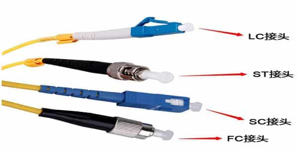
27. Fiber Connector: A device used to connect optical fibers. It is indispensable in fiber-optic communication systems and measuring instruments. It is different from fiber-optic fixed joints, can be disassembled, and is flexible to use, so it is also called fiber optic active connector or fiber optic movable joint. Generally, the optical fiber connector is required to have a small volume, small access loss, re-disassembly, high reliability, long life, and low price.

28. Optical attenuator: It is a device used to attenuate optical power. It is mainly used for index measurement of optical fiber systems, signal attenuation of short-distance communication systems, and system testing. The optical fiber jumper optical attenuator requires a lightweight, small volume, high precision, good stability, and convenient use. It can be divided into fixed, graded, and continuously adjustable

29. Optical amplification: refers to the realization of particle number inversion (except for nonlinear fiber amplifiers) under the action of pump energy (electricity or light), and then the amplification of incident light by stimulated radiation.

Disclaimer: All information indicated as other sources is transferred from other platforms, the purpose is to convey more information, does not represent the views and positions of this site. Please contact us if there is any infringement or objection.