Posted on Leave a comment

Fiber type

Fiber type

The following is a description of the most common types of communication fibers.

MMF (multimode fiber)

OM1 fiber or multimode fiber (62.5/125)

OM2/OM3 fiber (G.651 fiber or multimode fiber (50/125))

SMF (single-mode fiber)

– G.652 (dispersion non-displaced single-mode fiber)

– G.653 (dispersion-shifted fiber)

– G.654 (cutoff wavelength shifting fiber)

– G.655 (non-zero dispersion-shifted fiber)

– G.656 (low slope non-zero dispersion shifted fiber)

– G.657 (bend-resistant fiber)

As long as the optical budget allows, technically, any suitable fiber can be applied to FTTx technology, but the most commonly used fibers for FTTx technology are G.652 and G.657.

G.651 (multimode fiber)

G.651 is mainly used in local area networks and is not suitable for long-distance transmission. However, in the range of 300 to 500 meters, G.651 is a low-cost multimode transmission fiber.

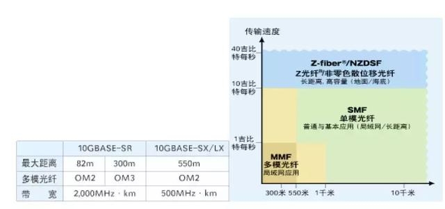
ITU-T G.651 fiber is OM2/OM3 fiber or multimode fiber (50/125). There is no OM1 fiber or multimode light (62.5/125) in the ITU-T recommended fiber.

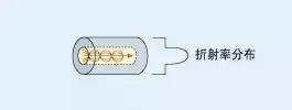
The reflectivity of the multimode fiber (50/125) core gradually changes from the center to the cladding, allowing multiple optical transmissions to be performed at the same speed.

G.652 fiber (dispersion non-displaced single-mode fiber)

The most common single mode fiber in the world. The dispersion that distorts the signal at a wavelength of around 1,310 nm can be minimized. You can use a 1550 nm wavelength working window for short-range transmission or with dispersion-compensating fiber or with a module.

G.652A/B is a basic single-mode fiber, and G.652C/D is a low-water peak single-mode fiber.

G.653 (dispersion-shifted fiber)

This fiber minimizes dispersion at around 1,550 nm, minimizing light loss.

G.654 (cutoff wavelength shifting fiber)

The official name of G.654 is a cut-off wavelength shifting fiber but is commonly referred to as a low-attenuation fiber. The low attenuation characteristics make G.654 fiber mainly used for long-distance transmission on the seabed or on the ground, such as 400 km transponder-free lines.

G.655 (non-zero dispersion-shifted fiber)

G.653 fiber has zero dispersion at 1,550 nm, while G.655 fiber has concentrated or positive or negative dispersion, which reduces the adverse effects of nonlinear phenomena that interfere with adjacent wavelengths in DWDM systems.

The first generation of non-zero dispersion-shifted fibers, such as PureMetro® fibers, have the advantage of having a dispersion of 5 ps/nm or less per kilometer, making dispersion compensation easier. The second generation of non-zero dispersion-shifted fibers, such as PureGuide® dispersion, reached around 10ps/nm per kilometer, doubling the capacity of DWDM systems.

G.656 fiber (low slope non-zero dispersion shifted fiber)

One of the non-zero dispersion-shifted fibers has strict requirements on the speed of dispersion, ensuring transmission performance over a larger wavelength range in DWDM systems.

G.657 (bend-resistant fiber)

The newest member of the ITU-T fiber family. New products based on the needs of FTTx technology and assembly applications.

G.657A fiber is compatible with G.652 fiber, and G.657B fiber does not need to be compatible with traditional single mode fiber.

Disclaimer: All information indicated as other sources is transferred from other platforms, the purpose is to convey more information, does not represent the views and positions of this site. Please contact us if there is any infringement or objection.

Posted on Leave a comment

Fiber construction

Fiber construction

The optical fiber for communication is composed of glass that transmits optical signals by total internal reflection. The glass fiber has a standard diameter of 125 microns (0.125 mm) and is covered with a resin protective coating of 250 microns or 900 microns in diameter. The central portion of the transmitted light of the glass fiber is called the “core”, and the cladding around it has a lower refractive index than the core, thereby limiting the loss of light.

Quartz glass is very fragile and therefore covered with a protective coating. There are typically three typical fiber coating layers.

Coating fiber at once

An optical fiber coated with a 0.25 mm diameter UV-curable acrylic coating. It is very small diameter increases the density of the fiber that can be accommodated in the cable and is very common.

Secondary coating fiber

Also known as tight buffer fiber or semi-tight buffer fiber. The surface of the fiber is covered with a thermoplastic resin having a diameter of 0.9 mm. It is more rugged and easy to operate compared to 0.25 mm fiber. Widely used in LAN cabling and fiber optic cables with a small number of fibers.

Ribbon fiber

The ribbon fiber improves the efficiency of the connector assembly and facilitates multi-core fusion, which improves work efficiency.

The ribbon fiber consists of 4, 8 or 12 differently colored fibers with a core count of up to 1,000. The fiber surface is covered with UV-curable acrylate material, which can be easily removed using standard fiber stripping pliers for easy multi-core fusion or removal of a single fiber. With a multi-core splicer, the ribbon fiber can be fused at one time and easily identified in a fiber optic cable with a large number of fibers.

Disclaimer: All information indicated as other sources is transferred from other platforms, the purpose is to convey more information, does not represent the views and positions of this site. Please contact us if there is any infringement or objection.

Posted on 2 Comments

Transceiver common faults and solutions

According to the daily maintenance and the problems that the users have summed up, I hope to bring some help to the maintenance staff, to determine the cause according to the fault phenomenon, to find the fault point, “the right medicine.”

1. What kind of connection is used when the transceiver RJ45 port is connected to other devices?

Cause: The RJ45 port of the transceiver is connected to the PC network card (DTE data terminal equipment) using a crossover twisted pair, and the HUB or SWITCH (DCE data communication equipment) uses parallel lines.

2. What is the reason why the TxLink light is not lit?

answer:

1, wrong twisted pair

2, the twisted pair crystal head is in poor contact with the equipment, or the quality of the twisted pair itself

3, the device is not connected

3. What is the reason why the TxLink lamp does not flash but is always on after the fiber is normally connected?

the reason:

1. The fault is generally caused by the transmission distance being too long;

2, compatibility issues with the network card (connected to the PC)

4. What is the reason why the Fxlink light does not illuminate?

the reason:

1. The fiber optic cable is connected incorrectly, and the correct connection method is TX-RX, RX-TX or fiber mode is wrong;

2. The transmission distance is too long or the intermediate loss is too large, exceeding the nominal loss of the product. The solution is to take measures to reduce the intermediate loss or replace it with a transmission distance longer.

3. The operating temperature of the fiber optic transceiver is too high.

5. What is the reason why the Fxlink light does not flash but is always bright after the fiber is connected normally?

Cause: The fault is generally caused by the transmission distance being too long or the intermediate loss is too large, exceeding the nominal loss of the product. The solution is to minimize the intermediate loss or replace it with a transceiver with a longer transmission distance.

6. What should I do if the five lights are all on or the indicator is normal but not transferable?

Reason: Generally, the power is turned off and restarted.

7. What is the ambient temperature of the transceiver?

Cause: The fiber optic module is greatly affected by the ambient temperature. Although it has its own built-in automatic gain circuit after the temperature exceeds a certain range, the optical power of the optical module is affected and decreased, which weakens the quality of the optical network signal and causes packet loss. The rate rises and even disconnects the optical link; (typical fiber optic modules can reach 70°C)

8. What is the compatibility with the external device protocol?

the reason:

Like the 10/100M switch, the 10/100M optical transceiver has a certain limit on the frame length, generally not exceeding 1522B or 1536B. When the switch connected at the central office supports some special protocols (such as Ciss ISL), The packet overhead is increased (the packet cost of the ISL of the Ciss is 30 Bytes), which is exceeded by the upper limit of the frame length of the optical transceiver. This indicates that the packet loss rate is high or not. In this case, the MTU of the terminal device needs to be adjusted. The overhead of the general IP packet is 18 bytes, and the MTU is 1500 bytes. Currently, the high-end communication equipment manufacturer has an internal network protocol, which generally adopts a separate packet method, which will increase the overhead of the IP packet. If the data is 1500 bytes, IP. After the packet, the size of the IP packet will exceed 18 and be discarded), so that the size of the packet transmitted on the line is satisfactory to the network device’s limitation on the frame length.

9. After the chassis has been working normally for a while, why is it that some cards are not working properly?

the reason:

Early chassis power supplies used relays. Insufficient power supply margin and large line loss are major problems. After the chassis works normally for a period of time, some cards may not work properly. When some cards are pulled out, the remaining cards work normally. After the long-term operation of the chassis, the connector oxidation causes a large joint loss. This power supply falls beyond the regulations. The required range may cause the chassis card to be abnormal. The power supply switching of the chassis is protected by a high-power Schottky diode to improve the form of the connector and reduce the power drop caused by the control circuit and the connector. At the same time, the power redundancy of the power supply is increased, which makes the backup power supply convenient and safe, and makes it more suitable for the long-term uninterrupted work.

10. What function does the link alarm provide on the transceiver?

Cause: The transceiver has a linked alarm function (linkless). When a certain fiber is dropped, it will be automatically fed back to the electrical port (that is, the indicator on the electrical port will also be extinguished). If the switch has network management, it will be reflected in the switch immediately. Network management software.

Disclaimer: All information indicated as other sources is transferred from other platforms, the purpose is to convey more information, does not represent the views and positions of this site. Please contact us if there is any infringement or objection.

Posted on Leave a comment

Network cable manufacturing method suitable for RJ45

Common network cable production!
Tools:
wire cutters (for connecting crystal heads) (required)
crystal head connection:
The color code and arrangement method of twisted pair is strictly regulated by international standards, and are now commonly used.

It is TIA/EIA568B. The following sequence should be used when wiring: (TIA/EIA568B)
1-> Orange White
2 -> Orange
3 -> Green White
4 -> Blue
5 -> Blue and White
6 -> Green
7 -> Brown White
8 -> Brown
, and using a one-to-one connection between the cables, a set of signals (negative voltage signals) will pass.

The two core wires that are not twisted together are transmitted, causing great near-end crosstalk
(NEXT-> Near-end-crosstalk), so they should be wired according to international standards!!

A local area network is a separate microcomputer or terminal that is connected to each other by communication lines and follows a certain protocol.

Exchange information and achieve resource sharing. Among them, communication lines,
that is, transmission media commonly used are twisted pair, coaxial cable, optical fiber, and the like. Starting from cost performance and maintainability,

Most local area networks use UTP-Unshielded
Twisted Pairs as the transmission medium for wiring.

The network cable consists of a twisted pair of long distances and a TransceiversRJ45  head. Twisted pair is divided into 4 pairs by 8 different color lines

Stranded together, the role of twisting into a team is to minimize the impact of electromagnetic radiation and external electromagnetic interference, twisted pair

It can be divided into a shielded twisted pair (STP) and unshielded twisted pair according to whether it is added with the shielding layer of metal mesh sleeve.

(UTP).
In the EIA/TIA-568A standard, twisted pairs are distinguished by electrical characteristics: Category 3, Category 4, and Category 5 lines. The internet

The most commonly used are the three types of lines and the five types of lines. Currently, there are more than six types of lines.
The third type of twisted pair cable is commonly used as data and voice transmission for 10Mbps Ethernet in LAN, in accordance with IEEE802.3

10Base-T standard. The fifth type of twisted pair currently occupies the largest LAN market, with a
maximum speed of 100Mbps, which is compliant with the IEEE802.3 100Base-T standard. Do a good network cable to RJ45Transceivers

The crystal head is connected to the RJ45 socket of the network device such as the network card or HUB. Correspondingly, the
The RJ45 connector is also classified into three or five types of electrical characteristics. RJ45 crystal head is made of sheet metal and plastic, especially

Need to pay attention to the pin serial number, when the metal piece faces us, the serial number from the left and right pins is 1-8,

It is very important when you are connected, you can’t make a mistake. The maximum transmission distance of the twisted pair is 100 meters.
Two twisted pair wire sequences 568A and 568B are specified in the EIA/TIA cabling standard.

Standard 568A: orange-white–1, orange–2, green-white–3, blue–4, blue-white–5, green–6, brown-white–7, brown–8;
standard 568B: Green-white–1, green–2, orange-white–3, blue–4, blue-white–5, orange–6, brown-white–7, brown–8.

Apply a wiring method throughout the network cabling, but the network connection of the RJ-45 plug at both ends is

Whether to use termination mode A. or termination mode B. is common in the network.
The order of the twisted pairs corresponds to the pin number of the RJ45 head. 10M Ethernet network cable uses 1, 2, 3, 6 number

The core wire transfers data and the 100M Ethernet network cable uses 4, 5, 7, and 8
numbered core wires to transmit data. Why do you now use 4 pairs (8-core) twisted pair? This is mainly to adapt to more

The scope of use can meet the wiring requirements of a wide range of user equipment without changing the infrastructure.

For example, we can use one of the twisted wires to achieve voice communication at the same time.

The provisions of the 100BASE-T4 RJ-45 pair twisted pair are as follows:

1, 2 for transmission, 3, 6 for the reception, 4, 5, 7, 8 are bidirectional lines.

Lines 1 and 2 must be twisted, 3, 6 twisted, 4, 5 twisted, 7 and 8 twisted.

Disclaimer: All information indicated as other sources is transferred from other platforms, the purpose is to convey more information, does not represent the views and positions of this site. Please contact us if there is any infringement or objection.

Posted on Leave a comment

Optical fiber communication development trend and challenges

Trend

FTTH can provide users with extremely rich bandwidth, so it has always been considered as an ideal access method. It plays an important role in realizing the information
society and needs to be promoted and constructed on a large scale. The fiber required for FTTH maybe two to three times that of existing coated fiber. In the past, due to the
the high cost of FTTH, the lack of broadband video services and broadband content, FTTH has not yet been mentioned on the agenda, only a small number of trials. Due
to the  advancement of optoelectronic devices, the price of optical transceiver modules and optical fibers has been greatly reduced; coupled with the relaxation of broadband
content, the practical process of FTTH has been accelerated.
Developed countries do not have the same view on FTTH: AT&T in the United States believes that the FTTH market is relatively small, and declared it at 0F62003: FTTH will
only have a market after 20-50 years. US operators Verizon and Sprint are more active, using FTTH to transform the network within 10-12 years. Japan’s NTT developed
FTTH at the earliest and has nearly 2 million users. China’s FTTH is in the pilot phase.

FTTH challenges

The widely used ADSL technology provides certain advantages in providing broadband services.
Compared with FTTH: 1 cheaper 2 use the original copper wire network to make the project construction simple 3 for the transmission of 1Mbps-500kbps film and television
programs can meet the demand. A large number of FTTH promotion is subject to restrictions.
For the broadband business to be developed in the near future, such as online education, online office, conference TV, online games, remote diagnosis, and other two-way
services and HDTV high-definition digital TV, ADSL is difficult to meet the asymmetric uplink and downlink transmission services. Especially HDTV, after compression, its
transmission rate still needs 19.2Mbps. It is being developed with H.264 technology and can be compressed to 5 to 6 Mbps. It is generally considered that the highest
transmission speed string of ADSL guaranteed for QOS is 2 Mbps, and it is still difficult to transmit HDTV. HDTV can be considered the main driving force of FTTH. That is,
when the HDTV service arrives, FTTH is not available.

FTTH solution

There are usually two types of P2P point-to-point and PON passive optical networks.
F2P solution one advantage: each user transmits independently, does not affect each other, and the system changes flexibly; cheap low-speed optoelectronic modules can be
used; the transmission distance is long. Disadvantages: In order to reduce the fiber and pipeline that users directly go to the office, it is necessary to place one active node of
the aggregate user in the user area.
PON solution – advantages: passive network maintenance is simple; in principle, optoelectronic devices and optical fibers can be saved. Disadvantages: expensive high-speed
optoelectronic modules need to be used; electronic modules that distinguish different user distances are needed to avoid conflicts between uplink signals of each user;
transmission distance is shortened by PON ratio; downlink bandwidth of each user is occupied by each other if user bandwidth is obtained When the guarantee is not
guaranteed, it is not only the network expansion but also the replacement of the PON and the replacement of the user module. (According to market prices, PEP is more
economical than PON)
There is a variety of PONs, generally as follows: (1) APON: ATM-PON, suitable for ATM switching networks. (2) BPON: Broadband PON. (3) OPEN: OFP-PON using general
frame processing. (4) EPON: PON using Ethernet technology, GPON is a PON of Gigabit Ethernet. (5) WDM-PON: Wavelength division multiplexing is used to distinguish
the user’s PON. Since the user is related to the wavelength, it is inconvenient to maintain and is rarely used in FTTH.
Wireless access technology is developing rapidly. It can be used as a WLAN IEEE802.11g protocol with a transmission bandwidth of up to 54 Mbps and coverage of more than
100 meters. If the wireless access WLAN is used for user data transmission, including uplink and downlink data and uplink data of the on-demand TV VOD, IEEE 802.11g
can be satisfied for the general user whose uplink is not large. The FTTH using optical fiber mainly solves the downlink transmission of HDTV broadband video, and of
course, it can also include some downlink data when needed. This forms a home network of “fiber to home + wireless access” (FTTH + wireless access). This kind of home
the network is particularly simple if PON is used. Because the PON has no uplink signal, there is no need for ranging electronic modules, and the cost is greatly reduced and
the maintenance is simple. If the user group of the PON is covered by the wireless metropolitan area network WiMAX (1EEE802.16), then it is not necessary to construct a
dedicated WLAN. The use of wireless in the access network is a trend, but the wireless access network still needs to be supported by the fiber optic network adjacent to the
user, which is similar to FTTH. FTTH+ wireless access is the future development trend.
Disclaimer: All information indicated as other sources is transferred from other platforms, the purpose is to convey more information, does not represent the views and
positions of this site. Please contact us if there is any infringement or objection.

Posted on Leave a comment

What are the specifications and types of fiber patch cords and fiber pigtails, and fiber patch cords and fiber pigtails?

Due to the variety of fiber patch cords and fiber pigtails, the problem of fiber patch cords and fiber pigtails often makes many friends unclear. In fact, the main difference between fiber patch cords and fiber pigtails is that only one end of the pigtail has The connector is connected, and the jumper has a connector at both ends, and the jumper is cut from the middle to be two pigtails. So, what are the specifications and types of fiber patch cords and fiber pigtails, fiber patch cords and fiber pigtails?

What are the specifications and types of fiber patch cords and fiber pigtail fiber patch cords and fiber pigtails?

1. What are fiber jumper and fiber pigtail?

The fiber jumper is a cable that is directly connected to a desktop computer or device to facilitate connection and management of the device. The jumper has a thick protective layer and is often used between the terminal box and the optical transceiver.

The fiber pigtail has a connector at one end and a fiber connector at the other end. It is connected to the core of other cables in a welded manner and is usually found in the fiber terminal box.

Second, the specifications and types of fiber patch cords and fiber pigtails

Jumpers are generally distinguished by single-mode and multi-mode in data transmission equipment. The color of the single-mode jumper is usually **, and there are two wavelengths, 1310nm and 1550nm respectively, and the transmission distance is 10km and 40km respectively; multimode jumper The color is usually orange, the wavelength is 850 nm, and the transmission distance is 500 m. According to the type of connector, it can be divided into the following types:

FC type jumper: round fiber optic connector, reinforced with the additional metal sleeve, fixed in the form of a turnbuckle.


SC type jumper: rectangular connector, fixed in the way of plugging and unloading, no need to rotate.


ST type jumper: round connector, with the snap-on connection, the fixed way is screw buckle.


LC type jumper: square connector, fixed in a convenient modular jack (RJ) latching principle.


The types of pigtails are mainly single-core pigtail, double-core pigtail, 4-core pigtail, 12-core bundle pigtail, 12-color bundle pigtail, SC bundle pigtail, FC bundle pigtail, LC bundle Pigtail and ST bundle pigtails. In addition to these, it can be divided into the following types:


Bundle pigtail: This pigtail is also known as the pigtail bundle. It consists of Corning tight-fitting fiber, aramid fiber reinforced components and flame-retardant PVC protective sleeve, compared to other types of pigtails. More popular and widely used.


Ribbon pigtail: The ribbon pigtail is the same as the bundle pigtail. Both are multi-core pigtails. The ribbon pigtail contains 12-core fiber. One end is used for welding and one end is equipped with a connector.


Armored pigtail: The outermost layer of this pigtail adds a metal protective cover to the conventional pigtail, so it is more durable than ordinary pigtails.


Fiber pigtail: low insertion loss, high return loss, good interchangeability, and repeated insertion and insertion, very convenient to use.


Waterproof pigtail: with a dense protective sleeve and waterproof sealing joint for use in harsh environments.


What are the specifications and types of fiber patch cords and fiber pigtails, fiber patch cords, and fiber pigtails? I believe that friends here have already answered this question. Of course, the use of fiber patch cords and pigtails also has many precautions. For example, the optical modules of the jumper connection must have the same wavelength of transmission and reception, and the pigtails are relatively slender and not resistant to high temperatures. and many more.


Disclaimer: All information indicated as other sources is transferred from other platforms, the purpose is to convey more information, does not represent the views and positions of this site. Please contact us if there is any infringement or objection.

Posted on Leave a comment

About MTP fiber patch cord

What is the MTP fiber patch cord?

MTP stands for Multi-Core Termination Push-In Connector, designed by Conec USA, and is a high-performance MPO connector with multiple innovative designs. The name of the MTP fiber patch cord comes from the MTP connector and is used for high-density connections between telecommunications room network equipment. This fiber patch cord provides a cost-effective solution for cabling systems with high performance, high density, and many other advantages.

MTP fiber jumper structure

MTP fiber patch cords are made up of MTP connectors, fiber optic cables, and other connectors, such as LC connectors or some MTP fiber patch cords. Fiber optic cables typically use OM3 and OM4, which are laser-optimized multimode fibers. Unlike traditional connectors, MTP/MPO connectors should be used with care to ensure proper connections.

MTP fiber patch cord type

According to different standards, MTP fiber jumpers are divided into multiple types. According to the number of cores, MTP fiber jumpers are divided into MTP single mode fiber jumpers and MTP multimode fiber jumpers. According to the connectors at both ends, there are mainly two configurations of MTP fiber jumpers. One is the MTP connection MTP, commonly referred to as the MTP backbone fiber patch cord. The other is MTP connected to a standard LC / FC / SC / ST / MTRJ connector (usually MTP-LC), which is commonly referred to as MTP branch fiber patch cord or MTP fan-out fiber patch cord.

Advantages of MTP fiber patch cord

The MTP fiber system is a truly innovative batch of products. The compact design of the MTP connector allows the MTP jumper core to be numerous and small, and the most commonly used are 12-core and 24-core. It is the same size as an SC connector and can deliver up to 12 fibers or 24, saving on circuit cards and rack space.


With the MTP trunk jumper, a complete fiber backbone can be installed without requiring any field termination. In addition, the MTP connector is fully compliant with all MPO connector standards and is compatible with VZ TPR.9431, IEC-61754-7, and EIA / ti A-604-5 and can be used to replace MPO connectors for better performance… It uses a simple push-pull latching structure for easy and intuitive insertion and removal.

MTP fiber patch cable application

MTP fiber patch cords can be used in a wide variety of applications. Such as backbone network, fiber optic wiring, high-density data center environment, warehouse, ribbon cable terminal, fast maintenance setup and playback system solutions, and parallel optical interconnection between servers.

Disclaimer: All information indicated as other sources is transferred from other platforms, the purpose is to convey more information, does not represent the views and positions of this site. Please contact us if there is any infringement or objection.

Posted on Leave a comment

G.652 fiber

G.652 fiber is single-mode fiber.


In the late 1970s, attempts were made to replace the LED source with a successful long-life semiconductor laser to achieve longer communication distances and greater communication capacity, but mode noise occurs when the laser is transmitted in a multimode fiber. In order to overcome the mode noise, in 1980, a single-mode fiber with a zero-dispersion point at 1310 nm (non-dispersion-shifted single-mode fiber, referred to as standard single-mode fiber) was successfully developed. ITU-T recommends that this single-mode fiber be defined as G. 652 fiber.


Because the design idea of a single-mode fiber is to pass only one mode, the mode noise that occurs when transmitting in a multimode fiber does not occur. Therefore, in the mid-1980s, the 140Mbit/s fiber-optic communication system consisting of a laser source and a standard single-mode fiber had a relay distance and transmission capacity far exceeding that of the coaxial cable transmission system, thus gradually replacing the copper cable with the fiber-optic communication system. Communication has become the main means of communication adopted by the telecommunications industry.


The G.652 recommendation is the first version of V1.0 (10/1984) created by ITU-T Group 15 (1981-1984 study period). Later, after 1988, 1993, 1997, and 2000, the V5.0 version was formed. In V5.0, the basic types of G.652 fiber were subdivided into G.652A and G.652B… At the ITU-T15 meeting held in Geneva in 2003 [V6.0 (03/2003)], two types of G.652C and G.652D were added, and it was clarified that the L-band was limited to 1625 nm.


In 2005, some parameters were further revised to form the V7.0 (05/2005) version. The main changes are: MFD tolerance is reduced, the maximum dispersion slope, concentricity error, cladding out-of-roundness, microbend loss are reduced, and the coarse-wavelength division multiplexing optical interface G.695 is added.

In the mid-1980s, a dispersion-shifted fiber (DSF, Dispersion-Shifted Fiber) with a zero-dispersion wavelength shifted from 1.3 μm to 1.55 μm was developed in the mid-1980s for the characteristics that attenuation and zero dispersion were not at the same operating wavelength. The ITU has coded this fiber as G.653.


However, the dispersion-shifted fiber has a dispersion of 1.55 μm at zero, which is not conducive to multi-channel WDM transmission. When the number of channels used is large, the channel spacing is small, and four-wave mixing (FWM) occurs at this time to cause crosstalk between channels. If the dispersion of the fiber line is zero, the interference of the FWM will be very serious; if there is trace dispersion, the FWM interference will decrease. In response to this phenomenon, a new type of optical fiber, namely non-zero dispersion fiber (NZ-DSF), G.655, has been developed.


The fiber has a minimum dispersion near 1.3μm, which is called zero-dispersion wavelength. This is the reason why the early fiber optic communication uses 1.3μm as the working wavelength. If the fiber material and the radius of the fiber core are changed, the zero-dispersion wavelength will have corresponding Change. People can use multi-clad fiber to adjust the zero dispersion wavelength in the wavelength range of 1.25–1.65μm.


The fiber that shifts the zero-dispersion wavelength by 1.3μm is called dispersion-shifted fiber.

Disclaimer: All information indicated as other sources is transferred from other platforms, the purpose is to convey more information, does not represent the views and positions of this site. Please contact us if there is any infringement or objection.

Posted on Leave a comment

Function of the indicator light of the optical transceiver and method for determining the fault

1. First, do you see if the indicator of the fiber transceiver or optical module and the twisted pair port indicator are on?

  A. If the optical port (FX-LINK/ACT) indicator of the transceiver is not lit, please confirm whether the fiber link is correct cross-link, fiber-optic jack TX-RX; RX-TX.

  B. If the optical port (FXFX-LINK/ACT) indicator of the A transceiver is on and the optical port (FXFX-LINK/ACT) indicator of the B transceiver is not lit, the fault is on the A transceiver side: one possibility is: The A transceiver (TX) optical transmission port is broken because the optical port (RX) of the B transceiver does not receive the optical signal; the other possibility is that the optical link of the A transceiver (TX) optical transmission port has Problem (the cable or fiber jumper may be broken).

  C. The twisted pair (TXFX-LINK/ACT) indicator does not light. Please make sure that the twisted pair cable is faulty or connected incorrectly. Please use the continuity tester (but some transceivers have twisted pair indicators). It must be lit after the fiber link is connected.)

  D. Some transceivers have two RJ45 ports: (To HUB) indicates that the connection line connecting the switches is a straight-through line; (To Node) indicates that the connection line connecting the switches is a cross-line.

  E. Some transceivers have an MPR switch on the side: the connection line connecting the switch is a straight-through mode; the DTE switch: the connection line connecting the switches is a cross-line mode.

  2. Is the optical cable and fiber jumper broken?

  A. The cable on/off detection: use laser flashlight, sunlight, illuminator to illuminate one end of the cable connector or coupler; see if there is visible light on the other end? If there is visible light, it means that the cable is not broken.

  B. Optical fiber connection continuity detection: use laser flashlight, sunlight, etc. to illuminate the fiber jumper; see if there is visible light on the other end? If there is visible light, the fiber jumper is not broken.

  3. Is there a mistake in the half/full duplex mode?

  Some transceivers have FDX switches on the side: full duplex; HDX switches: half duplex.

  4, using optical power meter instrument detection

  The luminous power of a fiber optic transceiver or optical module under normal conditions:

  Multimode 2Km: between -10db and 18db;

  Single mode 20 km: between -8 dB and 15 dB;

  Single mode 60 km: between -5db and 12db;

  If the luminous power of the optical transceiver is between -30db and 45db, then it can be judged that there is a problem with this transceiver.

Posted on Leave a comment

Fiber knowledge commonly used in weak current engineering

Fiber type

Optical cables are classified into indoor optical cables, outdoor optical cables, branch optical cables, and distribution optical cables depending on the application. Optical fibers can be divided into single mode and multimode according to the transmission mode, so monitoring generally uses single-mode fiber.

Single-mode fiber: An optical fiber that transmits only one mode optical signal. Conventionally, G.652, G.653, G.654, and G.655 are classified into transmission classes. Single-mode optical fiber transmits hundreds of megabits of signals up to several tens of kilometers.

Multimode fiber: A fiber that can transmit multiple modes of optical signals. It is G.651 grade. It is divided into OM1, OM2, and OM3 according to the optical mode. The maximum transmission distance of multi-mode fiber transmission is 100 kilometers.

Fiber laying method

Conventional outdoor optical cables are containers with loose tubes as the core, which is the most common fiber core laying method.

Indoor fiber optic cables are often laid tightly.

The core of the large-core optical cable also has a fiber core laminated in a strip form.

Cable structure

1 The most common cable structure is a layer-wound cable. The cable with more than 12 cores is generally of this kind. The cable cavity can accommodate multiple loose tubes, and the loose tube is the basic unit. Each loose tube can accommodate 6- 12-core core; the layer-wound cable is the center reinforcement member, and the loose tube is wrapped around the center reinforcement core. For practical applications, the core needs to be covered with different colors, a total of 12 colors, and the loose-layer cable is loose. The number of tubes is generally also less than 12, so the number of cores of the stranded cable is generally from 12 cores to 144 cores.

2 The structure of the outdoor optical cable below 12 cores is generally the center beam tube type. This type of optical cable has a central loose tube built in, which can contain 1-12 cores, and the outer sheath contains two parallel wires.

3 ribbon cable, also known as skeleton slot structure, is generally used as a cable structure with a large number of cores.

Fiber optic equipment

Optical fiber distribution frame (box): The fiber terminal box is used to protect the fiber and the pigtail. The pigtail is used to connect the fiber transceiver, fiber switch or optical transceiver.

Fiber optic terminal box (connector or splice tray): The fiber optic splice box fuses two fibers together.

Pigtail: One end of the fiber pigtail is fused to the fiber and the other end is connected to a fiber transceiver or fiber switch.

ODF fiber distribution frame and optocoupler: In some large and medium-sized monitoring projects, equipment such as ODF fiber distribution frame and optical coupler may be used. ODF optical distribution frame is mainly used in the equipment room, which can make many optical fibers more regular. Easy to maintain.

Optical fiber transceiver: Also known as the photoelectric converter, the device that converts the optical port and the electrical port is used in pairs. The electrical port is connected to the switch, and the optical port is connected to the fiber pigtail.

Fiber optic module: The main application of the fiber optic module and the fiber switch can directly connect the fiber pigtail to the switch through the fiber module, eliminating the fiber transceiver, but the price of the fiber switch is relatively high.

Disclaimer: All information indicated as other sources is transferred from other platforms, the purpose is to convey more information, does not represent the views and positions of this site. Please contact us if there is any infringement or objection.