Posted on Leave a comment

What are the classifications of fiber distribution frames?

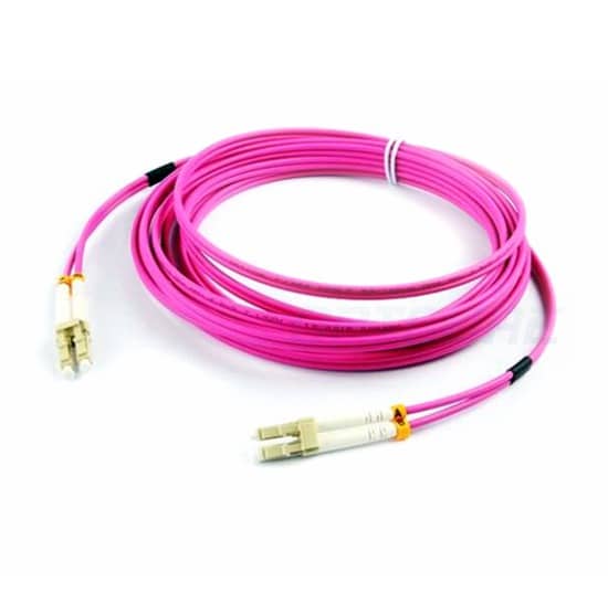
The optical fiber distribution frame is connected to the optical fiber connector. In the integrated wiring, the optical fiber distribution frame appears after the optical fiber appears, and the optical fiber generally appears in the vertical subsystem, then the problem comes, what is the optical distribution frame? classification? What are the functions of the fiber distribution frame? How to calculate the fiber distribution frame?


1. What are the classifications of optical distribution frames?

Unit type

A unitized fiber distribution frame is a unit in which multiple units are mounted, each unit is a separate fiber distribution frame. The patch panel not only retains the characteristics of the original small and medium-sized optical fiber distribution frame, but also provides space utilization through the structural deformation of the frame, and is a common structure in the early stage of the large-capacity optical fiber distribution frame. However, due to its inherent limitations in space provision, there is some inconvenience in operation and use.

Drawer type

The drawer type fiber distribution frame also divides a frame into a plurality of units, each unit consisting of one or two drawers. When welding and adjusting the thread, the corresponding drawer is pulled out to operate outside the rack, so that there is a large operation space, so that the units do not affect each other.

The drawer is provided with locking devices in both the pull-out and push-in states to ensure stable and accurate operation and safe and reliable connection of the components in the unit.

Although such a fiber distribution frame ingeniously provides a large space for the operation of the optical cable terminal, as with the unit type, the maximum convenience is not provided in the storage and deployment of the optical connection line. This type of rack is currently the most common form.

Modular

The modular structure divides the fiber distribution frame into a plurality of functional modules, the fusion, wiring, connection line storage and other functional operations of the optical cable are respectively completed in each module, and the modules can be assembled and installed in a common rack as needed. Inside. This structure provides maximum flexibility and better meets the needs of communication networks.

The modular high-capacity optical fiber distribution frame adopts a unique structure such as a panel and a drawer to make the welding and adjusting operation of the optical fiber more convenient. In addition, the vertical wire through and the intermediate distribution frame are used to effectively solve the cloth of the pigtail. Put and store problems. Therefore, it is the most popular type of large-capacity fiber distribution frame, but its cost is relatively high.

Second, what are the functions of the fiber distribution frame?

Optical fiber distribution frame plays an important role in the safe operation and flexible use of optical fiber communication networks, which are embodied in the following four aspects:

After the fiber jumper enters the rack, the fiber distribution frame can fix the fiber jumper to the frame, and mechanically fix the outer sheath and the reinforcing core to protect the fiber jumper from external mechanical damage.

The fiber distribution frame adopts a box structure, which saves space and optimizes cable management.

The high-density pre-terminated system used in fiber distribution frames enhances network performance and makes the network reliable and scalable.

Fiber distribution frames enable easy and fast deployment of high-density interconnects and cross-connects in the data center, simplifying cabling deployments, increasing wiring density, and effectively reducing cabling failures and making cabling flexible.

Third, how to calculate the fiber distribution frame

Take 6-core indoor multimode fiber and 24-port fiber distribution frame as an example:

Assuming there are a central computer room and 5-floor wiring closets, then it is certain that there are 5 fibers.

At this time, the fiber distribution frame is 5 (one per floor wiring) +1 (one in the central room) = 6

Center room fiber distribution frame = 4 (4 core fiber) * 5 (5 fibers) = 20, 20 < 24, so only one is enough, if it is 10 fibers, it is 4 * 10 = 40, 40<48, at this time the center room needs 2 lights.

There is also a situation that is often encountered in actual operation. On the first floor, there is a central computer room and a floor wiring closet. In this case, if everything is in the same cabinet, the fiber can be combined into the same optical distribution. . for example.

6-core indoor multimode fiber and 24-port fiber distribution frame, one central computer room and 5-floor wiring closets

If the central computer room and the floor wiring closet on the 1st floor are on the 1st floor, there are 24 fiber points on the 1st floor (4*5+4), just one 24-port light is enough, so this time We can also solve the problem with 5 light distributions.

Regarding the knowledge about optical fiber distribution frames, today’s Xiaobian will explain to you here first. It is also an extremely important and complicated task in the selection of optical fiber distribution frames. We should fully consider various situations according to specific situations. Factors, based on repeated comparisons, can select a fiber distribution frame that best meets current needs and future development.

(This article is from the Internet, compiled and edited by thousands of hackers. If there is any infringement, please contact to delete.)

This article was first published in the thousand integrated wiring network: http://cabling.qianjia.com/html/2019-04/24_334470.html

Disclaimer: All information indicated as other sources is transferred from other platforms, the purpose is to convey more information, does not represent the position and position of the site and is responsible for its authenticity. If there is any infringement or objection, please contact us to delete.

Posted on Leave a comment

Fiber optic knowledge

Fiber optic knowledge

1 The tensile strength of the fiber is very high, close to the tensile strength of the metal;

2 The ductility of the fiber (1%) is worse than that of the metal (20%);

3 When there are cracks in the fiber, bubbles or debris, under certain tension, it is easy to break;

4 fiber rainwater is easy to break, and the cutting loss is greatly increased;

5 Loss increases with decreasing temperature at low temperatures;

6 Fibers need to be protected from mechanical properties and require waterproof protection to ensure transmission performance.

Wavelength: Communication window of optical fiber communication optical signal, wherein 850, 1310nm is a multi-mode fiber communication window, which is a short-wavelength window; 1310, 1550, 1640nm, etc. is single-mode optical fiber communication with a long-wavelength window.

Simplex: The signal on the communication is only received or not sent, and the one-way communication is understood to be that only one optical fiber is received or only the optical signal is transmitted.

Duplex: Both receiving signals and transmitting signals, which are divided into half-duplex and full-duplex. Half-duplex can be understood as a core optical core. After receiving the signal, the signal can be sent through the same core fiber, but only at this time. Can not send signals cannot be received; and full-duplex is still using a core fiber while receiving signals can continuously send signals, receiving and transmitting two kinds of communication without interference, generally through frequency division multiplexing, time division multiplexing and waves Divided by multiplexing.

Disclaimer: All information indicated as other sources is transferred from other platforms, the purpose is to convey more information, does not represent the views and positions of this site. Please contact us if there is any infringement or objection.

Posted on Leave a comment

What do the six indicators of the fiber transceiver mean?

Our commonly used fiber optic transceivers have 6 indicators, so what does each indicator mean? Is it true that all the indicators are lit to indicate that the fiber transceiver is working properly?

  PWR: Lights up to indicate that the DC5V power supply is working properly.

  FDX: Lights up to indicate that the fiber transmits data in full duplex mode;

  FX 100: Lights up to indicate that the optical fiber transmission rate is 100Mbps;

  TX 100: The light is on, indicating that the twisted pair transmission rate is 100 Mbps, and the light is off, indicating that the twisted pair transmission rate is 10 Mbps;

  FX Link/Act: The long light indicates that the fiber link is connected correctly; the flashing light indicates that data is being transmitted in the fiber;

  TX Link/Act: The long light indicates that the twisted pair link is connected; the light flashes to indicate that there is data in the twisted pair that is transmitting 10/100M.

  If the optical transceiver is working properly, the PWR power indicator must be steady on. The FX-LINK/ACT fiber link indicator and the TX-LINK/ACT network link indicator must be on or blinking. If the LINK/ACT indicator is off. Check whether the link is normal. The FDX working mode indicator, FX-100 fiber rate indicator and TX-100 network rate indicator are not on the fiber transceiver.

Disclaimer: All information indicated as other sources is transferred from other platforms, the purpose is to convey more information, does not represent the views and positions of this site. Please contact us if there is any infringement or objection.

Posted on Leave a comment

Introduction of optical fiber

1 Overview

Fiber and coaxial cables are similar except that there is no mesh shield. The center is the light-transmitting glass core. In a multimode fiber, the core has a diameter of 15 mm to 50 mm, which is roughly equivalent to the thickness of a human hair. The single-mode fiber core has a diameter of 8 mm to 10 mm. The outside of the core is surrounded by a glass envelope having a lower index of refraction than the core to maintain the fiber within the core. Next to it is a thin plastic jacket to protect the envelope. The fiber is usually bundled and protected by an outer casing. The core is usually a double-layer concentric cylinder made of quartz glass with a small cross-sectional area, which is brittle and easily broken so that a protective layer is required. Its structure is shown in Figure 1.

The fiber on the land is usually buried 1 meter underground, sometimes damaged by underground small animals. Near the coast, the transoceanic fiber casing is buried in the ditch. In deep water, they are at the bottom and are most likely to be bitten by fish or crashed by fishing boats.

2, classification

Optical fiber is mainly divided into the following two categories:

1) Transmission point modulus class

Transmission point analog-to-digital single mode Fiber (Single Mode Fiber) and multimode fiber (Multi-Mode Fiber). The single-mode fiber has a small core diameter and can only be transmitted in a single mode at a given operating wavelength, with transmission bandwidth and large transmission capacity. Multimode fiber is an optical fiber that can transmit simultaneously in multiple modes at a given operating wavelength. Multimode fiber has poorer transmission performance than single mode fiber.

2) Refractive index distribution class

Refractive index distribution fibers can be classified into hopping fibers and grading fibers. The refractive index of the hopping fiber core and the refractive index of the protective layer are both constant. At the interface between the core and the protective layer, the refractive index changes stepwise. The refractive index of the graded fiber core decreases with a certain radius as the radius increases and decreases to the refractive index of the protective layer at the interface between the core and the protective layer. The change in the refractive index of the core approximates the parabola. The refractive index distribution type fiber beam transmission is shown in Fig. 2.

3, the connection method

There are three ways to connect the fiber. First, they can be plugged into the connector and plugged into a fiber optic socket. The connector loses 10% to 20% of the light, but it makes it easy to reconfigure the system.

Second, it can be joined mechanically. The method is to place one end of two carefully cut fibers in a sleeve and then clamp them. The fiber can be adjusted through the junction to maximize the signal. The mechanical combination requires trained personnel to take about 5 minutes to complete, and the loss of light is about 10%.

Third, the two fibers can be fused together to form a solid connection. The fiber formed by the fusion method is almost the same as the single fiber, but it also has a little attenuation. For all three connection methods, there is a reflection at the junction and the reflected energy interacts with the signal.

4, send and receive

There are two types of light sources that can be used as signal sources: light-emitting diodes (LEDs) and semiconductor lasers (LDs). They have different characteristics, as shown in the following table.

projectledSemiconductor laser
Data ratelowhigh
modeMultimodeMultimode or single mode
distanceshortlong
Life cyclelongshort
Temperature sensitivitySmallerMore sensitive
CostLow costexpensive

The receiving end of the fiber is made up of a photodiode that gives a point pulse when it encounters light. The response time of a photodiode is typically 1 ns, which is why the data transfer rate is limited to 1 Gb/s. Thermal noise is also a problem, so the light pulse must have enough energy to be detected. If the pulse energy is strong enough, the error rate can be reduced to a very low level.

5, the interface

There are two types of interfaces currently in use. The passive interface is formed by two streets fused to the main fiber. One end of the connector has a light emitting diode or laser diode (for transmission). At the other end, there is a photodiode (for receiving). The joint itself is completely passive and therefore very reliable.

Another type of interface is called an active repeater. The input light is converted into an electrical signal in the repeater, and if the signal has been attenuated, it is re-amplified to the maximum intensity, then converted to light and sent out. Connected to the computer is a common copper wire that enters the signal regenerator. There is now a pure optical repeater that does not require optoelectronic conversion and can, therefore, operate at very high bandwidth.

Disclaimer: All information indicated as other sources is transferred from other platforms, the purpose is to convey more information, does not represent the views and positions of this site. Please contact us if there is any infringement or objection.

Posted on Leave a comment

What is the difference between a transmission optical port and an electrical port?

Optical port
The optical port is an abbreviation of the optical fiber interface.
Also known as G port (meaning G fiber port)
Optical port: A fiber-optic bandwidth interface used in large equipment such as equipment rooms and cabinets.

Fibers can be used for audio (sound card with light output), network (fiber as a transmission medium), disk (fiber instead of cable for data transmission), and more.
Optical fibers can be divided into single-mode fibers and multimode fibers. The differences are as follows:
Single mode fiber and multimode fiber can be easily discriminated from the size of the core. The core of a single-mode fiber is small, about 4 to 10 um, and only transmits the main mode. This completely avoids modal dispersion and makes the transmission band wide.

The transmission capacity is large. This fiber is suitable for high-capacity, long-distance fiber-optic communications. It is an inevitable trend in the future development of optical fiber communication and lightwave technology.
Multimode fibers are further classified into multimode abrupt fibers and multimode graded fibers. The former has a larger core diameter and more transmission modes, so the bandwidth is narrower and the transmission capacity is smaller;
In the latter core, the refractive index decreases as the radius increases, and a relatively small modal dispersion can be obtained, so that the frequency band is wider and the transmission capacity is larger. Currently, the latter is generally applied.
Since the transmission speeds of different modes of light in a multimode fiber are different, the transmission distance of the multimode fiber is short. Single-mode fiber can be used in non-relay optical communication.

In the theory of optical fiber communication, the optical fiber has single mode and multimode, and the difference lies in:
1. Single-mode fiber has a small core diameter (about 10m), allowing only one mode of transmission, low dispersion, and working at long wavelengths (1310nm and 1550nm), which is relatively difficult to couple with optical devices.
2. The multimode fiber has a large core diameter (62.5m or 50m), allowing transmission in hundreds of modes, large dispersion, and operating at 850nm or 1310nm. Coupling with optical devices is relatively easy.
For the optical module, strictly speaking, there is no single mode or multiple modes. The so-called single-mode, multi-mode module refers to the optical device used by the optical module to match the fiber to obtain the best transmission characteristics.

Generally, there are the following differences:
1. Single-mode modules generally use LD or narrow-spectrum LEDs as the light source. The size of the coupling components is good with single-mode fiber. When transmitting with single-mode fiber, it can transmit longer distances and the price is higher.
2. Multi-mode modules generally use lower-priced LEDs as the light source. The size of the coupling components is well matched with multimode fibers, and the price is relatively cheap.

The electrical port is relative to the optical port and refers to the physical characteristics of the fire extinguisher. It mainly refers to the copper cable and is the processed electrical signal. Currently, the common network interfaces include 100M electrical ports and Gigabit electrical ports.

Simply put, the electrical port is an ordinary network cable interface, the general speed is 10M or 100M, and some support 1000M. The maximum distance of the electrical port is 100 meters.

Disclaimer: All information indicated as other sources is transferred from other platforms, the purpose is to convey more information, does not represent the views and positions of this site. Please contact us if there is any infringement or objection.

Posted on Leave a comment

How to install fiber optic cable

The way of entering home


User room wiring

In the FTTH project, the user’s indoor wiring is the most complicated part, and many factors are considered. It is necessary to ensure the safety of the line, but also to take

into account the indoor beauty, but also to facilitate the construction. The traditional single-core indoor optical cable cannot meet the requirements of the current FTTH

engineering indoor wiring. As a substitute for traditional indoor optical cable, Weipuxin leather cable can adapt to most indoor wiring conditions, such as turning at a

bending radius of 20mm, which can bear the side pressure of people stepping on the cable, and the drag of engineering construction. pull. At the same time, with a variety of

field connectors, real-time end-to-end and docking can be achieved in the shortest time. Therefore, Weipuxin leather cable is the best choice for FTTH indoor wiring.


Vertical horizontal wiring in the building


Like the user’s indoor wiring, the Weipuxin cable is also suitable for vertical horizontal wiring in the building. Horizontal cabling is not very demanding on fiber optic cable,

but vertical cabling must require fiber optic cable to have a certain tensile strength. The lipoxin leather cable can withstand a short-term 200 Newton and long-term 100Newton pulls, so it can guarantee the safety and stability of the vertical wiring of the cable optical cable within a certain height range.


Self-supporting overhead wiring


The self-supporting “8” word wiring cable has a tensile strength and can withstand a span of 50 meters due to its metal suspension unit. The optical cable is laid out in an

overhead manner. The metal suspension unit is cut off before being placed in the house and is fixed on a special fixture. The remaining optical cable is stripped of the metal

suspension wire and then introduced into the room by a leather cable.


Pipeline wiring

Because the pipeline mapping cable is harder than the sheath cable, the tensile strength is higher, and the cable contains water blocking material, which can reduce outdoor rain erosion, so it is suitable for long-distance outdoor pipeline laying. The Vision Information Pipeline Mapping Cable uses an all-metal structure to avoid the introduction of lightning into the room. After the optical cable enters the household, the outer sheath, the water blocking material and the reinforcing member are stripped, and the indoor heating cable is directly used for the indoor wiring, which inherits all the advantages of the indoor wiring of the sheath optical cable, and reduces the connection of the outdoor-indoor optical cable.


Disclaimer: All information indicated as other sources is transferred from other platforms, the purpose is to convey more information, does not represent the views and positions of this site. Please contact us if there is any infringement or objection.

Posted on Leave a comment

Fiber Optic Communications Professional Overview

Optical fiber communications have emerged as one of the main pillars of modern communications and have played a pivotal role in modern telecommunications networks. As an emerging technology, optical fiber communication has developed rapidly in recent years and is widely used in the history of communication. It is also an important symbol of the world’s new technological revolution and the main transmission tool for various information in the future information society.


Professional Overview

The fiber optical is the abbreviation of the optical fiber. Optical fiber communication is a communication method in which light waves are used as information carriers and optical fibers are used as transmission media. In principle, the basic material elements that makeup fiber optic communication are fiber optics, light sources, and photodetectors. In addition to classification according to the manufacturing process, material composition, and optical characteristics, optical fibers are often classified according to their applications and can be classified into communication optical fibers and sensing optical fibers. The transmission medium fiber is divided into two types: general purpose and special purpose, and the function device fiber refers to an optical fiber for performing functions of amplification, shaping, frequency division, frequency multiplication, modulation, and optical oscillation of light waves, and is often used for a certain functional device. The form appears.


Optical fiber communication is a communication method in which optical waves are used as carriers and optical fibers are used as transmission media to transmit information from one place to another. This is called “wired” optical communication. Today, the optical fiber has become the main transmission method in the world communication because of its transmission bandwidth, high anti-interference and low signal attenuation, which is far superior to cable and microwave communication.


In 1966, British Chinese sorghum (Charles Kao) published a paper on the use of quartz to make glass filaments (fibers) with a loss of up to 20dB/km, enabling high-capacity fiber-optic communication. At that time, only a few people in the world believed, such as the British Standard Telecommunications Laboratory (STL), the United StatesCorning Glass Company, Bell Labs and other leaders.


In 2009, Gao Song won the Nobel Prize for inventing fiber. In 1970, Corning developed a quartz fiber with a loss of 20dB/km and a length of about 30 m, which was said to cost $30 million. In 1976, Bell Labs established an experimental circuit in Atlanta, Washington, with a transmission rate of only 45 Mb/s, which can only transmit hundreds of telephones, while a medium-coaxial cable can transmit 1800 telephones. Because when it is fashionable to use a laser for communication but to use a light-emitting diode (LED) as a light source for optical fiber communication, the rate is very low.


Around 1984, the semiconductor laser for communication was successfully developed. The speed of optical fiber communication reached 144 Mb/s, and 1920 telephones could be transmitted. In 1992, a fiber-transmission rate reached 2.5Gb/s, which is equivalent to more than 30,000 telephones.


In 1996, lasers of various wavelengths were successfully developed to realize multi-wavelength multi-channel optical fiber communication, so-called “wavelength division multiplexing” (WDM) technology, that is, transmitting optical signals of multiple different wavelengths in one optical fiber… Thus, the transmission capacity of optical fiber communication is doubled.


In 2000, with WDM technology, a fiber-optic fiber-transmission rate reached 640 Gb/s. Some people invented the fiber in 1976, and there was a big doubt about winning the Nobel Prize in 2010. In fact, it can be seen from the history of the above optical fiber that despite the large capacity of the optical fiber, the high-speed laser and microelectronics cannot function as the ultra-large capacity of the optical fiber. The speed of electronic devices has reached the gigabit/second level, and the emergence of high-speed lasers of various wavelengths has enabled the transmission of optical fibers to the order of terabits/second (1Tb/s = 1000 Gb/s). Triggered a revolution in communication technology!”


Disclaimer: All information indicated as other sources is transferred from other platforms, the purpose is to convey more information, does not represent the views and position of this site. Please contact us if there is any infringement or objection.

Posted on Leave a comment

Fiber optic communication applications and work processes

Work Process

Send: The CPU serializes the parallel data through a dedicated IC chip and inserts the corresponding bit code (start, stop, check digit, etc.) according to the communication format and the signal is sent to the fiber connector by the output terminal TXD. Then, the light source in the optical fiber connector performs the electro-optical conversion and the converted optical signal transmits an optical signal to the optical fiber through the optical fiber plug, and the optical signal propagates forward in the optical fiber.

Receiving: the optical signal from the optical fiber is sent to the receiver of the fixed plug through the moving plug of the optical fiber connector, and the receiver optically-electrically restores the received optical signal, thereby obtaining a corresponding electrical signal, and the electrical signal is sent to The RDX input terminal of the dedicated IC chip is converted to parallel data by the dedicated IC chip and then transmitted to the CPU.

Application field

The application fields of optical fiber communication are very wide, mainly used for local telephone trunk lines. The advantages of optical fiber communication can be fully utilized here, and the cable is gradually replaced, which is widely used. Also used for long-distance trunk communication in the past mainly relying on cable, microwave, satellite communication, and now gradually use fiber-optic communication and form a globally advantageous bit transmission method; for global communication networks, public telecommunications networks of various countries (such as China’s national one) Level trunk line, provincial secondary line and sub-sector branch line).

It is also used for high-quality color TV transmission, industrial production site monitoring and dispatching, traffic monitoring, and control command, town cable TV network, shared antenna(CATV) system, Used in fiber optic LANs and others such as in aircraft, in spacecraft, in ships, undermines, in the power sector, in military applications, and in corrosive and radiative applications.

The optical fiber transmission system mainly consists of an optical transmitter, an optical receiver, an optical cable transmission line, an optical repeater, and various passive optical components. To communicate, the baseband signal must be further electrical terminals of the unit after the signal processing to the optical fiber transmission system to complete the communication process.

It is suitable for use in fiber optic analog communication systems, but also for fiber optic digital communication systems and data communication systems. In the optical fiber an analog communication system, the electrical signal processing refers to the processing of amplifying and pre-modulating the baseband signal, and the electrical signal processing is the inverse process of the originating processing, that is, demodulation, amplification, and the like.

In the optical fiber digital communication system, electrical signal processing refers to amplification, sampling, and quantization of the baseband signal, that is, pulse code modulation (PCM) and line code type encoding processing, and the electrical signal inverse processing is also the inverse process of the originating end. For data fiber communication, electrical signal processing mainly involves amplifying the signal. Unlike digital communication systems, it does not require pattern conversion.

Posted on Leave a comment

Comparison of fiber optic patch cords OM1, OM2, OM3 and OM4

As is well known, “OM” stands for optical multi-mode, that is, optical mode is a standard for multimode fiber to represent fiber grade. The bandwidth and maximum distance are different when transmitting at different levels, but there are often friends who have doubts about the difference between the optical fiber jumpers OM1, OM2, OM3, and OM4. Let Xiaobian explain the fiber jumpers OM1 and OM2 for everyone. The difference between OM3 and OM4.

LC-LC OM4 Duplex Fiber Cable

What is the difference between fiber optic patch cords OM1, OM2, OM3, and OM4?

1. Comparison of parameters and specifications of OM1, OM2, OM3 and OM4 fibers

1. OM1 refers to a 50um or 62.5um core-diameter multimode fiber with a full injection bandwidth of 200/500MHz.km at 850/1300nm;

2. OM2 refers to a 50um or 62.5um core-diameter multimode fiber with a full injection bandwidth of 500/500MHz.km at 850/1300nm;

3. OM3 is an 850nm laser-optimized 50um core-diameter multimode fiber. In 10Gb/s Ethernet with 850nm VCSEL, the fiber transmission distance can reach 300m.

4. OM4 is an upgraded version of OM3 multimode fiber, and the fiber transmission distance can reach 550m.

Second, the design comparison of OM1, OM2, OM3, and OM4 fiber

1. The traditional OM1 and OM2 multimode optical fibers are based on LED (Light Emitting Diode) as the basic light source, and OM3 and OM4 are optimized on the basis of OM2, making them suitable for the light source. For the transmission of LD (Laser Diode);

2. Compared with OM1 and OM2, OM3 has a higher transmission rate and bandwidth, so it is called optimized multimode fiber or 10G multimode fiber;

3, OM4 re-optimized on the basis of OM3, with better performance.

Third, the function and characteristics of OM1, OM2, OM3, and OM4 fiber

1. OM1: large core diameter and numerical aperture, strong light collecting ability and bending resistance;

2, OM2: core diameter and numerical aperture are relatively small, effectively reducing the mode dispersion of multimode fiber so that the bandwidth is significantly increased, the production cost is also reduced by 1/3;

3, OM3: the use of flame-retardant skin, can prevent the spread of flame, prevent the emission of smoke, acid gases, and toxic gases, and meet the needs of 10 GB / s transmission rate;

4. OM4: Developed for VSCEL laser transmission, the effective bandwidth is more than double that of OM3.

Fourth, the application comparison of OM1, OM2, OM3, and OM4 fiber

1. OM1 and OM2 have been widely deployed in buildings for many years, supporting Ethernet transmission with a maximum of 1GB;

2, OM3 and OM4 fiber optic cable is usually used in the hiring environment of the data center, supporting the transmission of 10G or even 40/100G high-speed Ethernet road.

5. When do you use OM3 fiber jumpers?

OM3 fiber is designed to work with VCSEL and meets the ISO/IEC11801-2nd OM-3 fiber specification to meet the needs of 10 Gigabit Ethernet applications. There are many types of OM3 fiber, including indoor type, indoor/outdoor versatility, etc. The number of cores of the fiber is from 4 cores to 48 cores. It also supports all applications based on older multimode 50/125 fiber, including support for LED sources and laser sources.

1. The transmission distance of Gigabit Ethernet using OM3 fiber system can be extended to 900 meters, which means that users do not have to use expensive laser devices when the distance between buildings is more than 550 meters.

2. Within the distance of 2000 meters, standard 62.5/125μm multimode fiber can be used in all cases within the OC-12 (622Mb/s) rate range, and single-mode fiber will be used. However, the emergence of OM3 multimode fiber has changed this situation. Since OM3 fiber can increase the transmission distance of Gigabit and 10 Gigabit systems, the use of 850 nm wavelength optical module in conjunction with VCSEL will be the most cost-effective cabling solution.

3. When the link length exceeds 1000 meters, single-mode fiber is still the only choice. Single-mode fiber can achieve 5 km transmission distance at 1310 nm in Gigabit system, and 10 km in 10 Gigabit system. Transmission distance.

4. When the link length is less than or equal to 1000 meters, OM3 50μm multimode fiber can be used in the Gigabit system, and single-mode fiber should be used in the 10G system.

5. When the link length is less than 300 meters, OM3 multimode fiber can be applied to any Gigabit and 10 Gigabit systems.

6. When do you use OM4 fiber patch cords?

For a typical link, the cost of an optical module is about expensive. Although single-mode fiber is cheaper than multimode fiber, the use of single-mode fiber requires a very expensive 1300nm optical module, which costs about 2-3 times that of an 850nm multimode optical module. In general, a multimode fiber The system cost is much lower than that of a single-mode fiber system.

When investing in fiber-optic cabling, if you can consider adding some initial investment in wiring, using better multimode fiber, such as OM4 fiber, you can ensure that the current multi-mode fiber technology is fully utilized to reduce the overall cost of the current system; When upgrading to higher speed systems, such as 40G and 100G, OM4 is still available and will be more cost-effective.

In summary, when the transmission rate is greater than 1 Gb/s, the use of multimode fiber is a good system choice. When the system requires a higher transmission rate, the following are the guidelines for our choice of OM4 fiber:

1. For Ethernet users, the transmission distance can reach 300m to 600m in 10Gb/s system transmission; in 40Gb/s and 100Gb/s systems, the transmission distance is 100m to 125m.

2. For campus network users, OM4 fiber will support 4Gb/s fiber link length of 400m, 8Gb/s fiber link length of 200m or 16Gb/s fiber link length of 130m.

to sum up

Multimode fiber technology has evolved from OM1 multimode to OM4, which now supports 10Gbps, which will give users the most effective return on investment and become the best choice for backbone cabling or fiber to the desktop. After reading this article, I believe I have already answered your questions about the difference between the fiber jumpers OM1, OM2, OM3, and OM4.

Disclaimer: All information indicated as other sources is transferred from other platforms, the purpose is to convey more information, does not represent the views and positions of this site. Please contact us if there is any infringement or objection.

Posted on Leave a comment

Do you know these ways to clean fiber cable and fiber accessories?

With the development of scientific and technological technology, “optical fiber into the household”, “smart city” and other projects, optical fiber and fiber optic accessories are more and more widely used. But there are always minor problems in fiber optic accessories, and these little problems don’t seem to matter. But if there is an “in case”, the price to be brought to us will be enormous. Therefore, regardless of the consideration, we need to minimize the risk.

If a friend who has just come into contact with fiber optic products will have questions, fiber optic products already have a dust cover, why do you need to clean them before testing and using them? Here’s a look at it: Fiber optic connectors, jumpers, tail fibers, and adapters all carry dust caps when they are shipped. The effect of the dust cap in addition to ensuring that the connector is clean, the main purpose is to protect the fiber connector end surface, to avoid direct contact with the connector end surface and damage the connector. Dust caps can only be removed if they are installed, tested, and used. Once the dust cap is removed, the fiber optic connector must be coupled with another clean fiber connector.

As a result, it would be wrong to assume that “there is a dust cap protection that does not need to be cleaned before use”. Because it is not possible to determine whether the end surface is clean before the dust cap is covered, the dust cap itself must be clean. Good construction habits require that fiber optic connectors be cleaned even if a dust cap exists. When a fiber link is finished testing, install the dust cap immediately, otherwise, the link must be re-tested before use.

As far as the current situation is concerned, the main way of optical fiber cleaning is the use of alcohol and non-woven cleaning, you can choose ordinary industrial alcohol, with non-fiber sponge paper or non-woven cloth wipe. In addition, you can also choose optical fiber cleaning liquid, professional fiber cleaning liquid with non-toxic, tasteless, flame retardant, insulation, rapid evaporation, and other characteristics, the price is higher than alcohol, suitable for use in the machine room has been put into use, as well as the environment requirements are relatively high occasions.